Troubleshooting Common Problems with the Commodore PET 2001
As a seller of replacement parts for the original Commodore PET 2001, I am frequently asked questions like “My PET won’t boot. Will your (fill in product here) fix it?”. I usually answer these questions are some troubleshooting steps / tips that the potential customer can use to try to narrow down the problem, but after having answered essentially the same question dozens of times, I decided to put together this article so that all my collected knowledge on problems with the PET can be found in one place. What follows stems mostly from my experience putting back together the pieces of an incomplete Commodore PET 2001-8 that I tore apart as a small child augmented with what I have learned from helping customers troubleshoot their Commodore PET computers and from designing my various Commodore PET replacement parts. It is NOT intended to be comprehensive, just to outline troubleshooting techniques for some of the more common problems with the PET.
Background / Scope
This article applies ONLY to the ORIGINAL 1977 Commodore PET 2001-8! In short, if your PET does not have a cassette drive built in and a chicklet keyboard, then this article does not apply to your hardware. I have never worked on one of these newer PETs, my parts do NOT work with them, and I know essentially nothing about them. If you have one that doesn’t work, all I can offer is that I will work on it ($50/hr) if you ship it to me. Contact me if you are interested in this service.
Even if you do have an original 1977 Commodore PET 2001-8, do note that there were multiple variants of the motherboard. The first version used MPS6540 ROM chips and MPS6550 RAM chips. Later versions substituted 2316B ROM chips in place of th3 6540’s and/or 2114 RAMs in place of the 6550s. In all four variants were made. This article applies directly to the original 6540 / 6550 version since that is the most common variant and the one that I have the most experience with. The others should work similarly and I have noted differences where I know them to exist. However, be aware that things may not work exactly the same if you have 2316B ROMs or 2114 RAMs.
Finally, this article assumes that you know at least basic electronics. If you don’t, please, stop now before you damage something or hurt yourself and let me repair your PET for you.
Other Resources
There are many other resources on the web that can help you. Google is your friend here, but some of my favorites are listed below.
Complete Schematics for all variants of the 2001:
http://www.zimmers.net/anonftp/pub/cbm/schematics/computers/pet/2001/
ROM images for all variants of the 2001:
http://www.zimmers.net/anonftp/pub/cbm/firmware/computers/pet/index.html
Users Manuals:
http://www.commodore.ca/commodore-manuals/
The PETvet – This is an expansion board that mounts between the CPU and the motherboard of the PET. It allows you to bypass the RAM and/or ROM on the PET motherboard. The creator advertises it as a permanent solution to failed RAM / ROM, but I think it is better to use it as a troubleshooting aid and then once the problem is found, replace only the failed components, leaving the rest of the pet original. In either case, it is a useful tool:
http://www.bitfixer.com/bf/petvet
And last but not least, here are my PET related products:
http://www.dasarodesigns.com/product-category/pet/
Before you Begin
Before troubleshooting a Commodore PET 2001, it is essential to note that the process will involve repeatedly turning the computer off and on. This is extremely hard on the internal monitor circuitry and can cause it to fail in short order. Furthermore, some of the tests require that you look at what is on the screen after power is turned on but before the CPU is reset. This is only easily possible with an external monitor as the internal monitor comes on too slowly. Thus, I strongly recommend that your purchase one of my Commodore PET Video mixers before beginning a PET troubleshooting project.
Also be aware that the chips used in the Commodore PET, especially the RAM chips, are highly sensitive to static electricity. Thus I recommend wearing a static dissipative bracelet when working on the machine, or at very least being careful to always touch the chassis before touching the board.
The sockets used in the PET 2001 motherboard are notorious for bad contacts. Thus, before spending a long time on troubleshooting, I recommend removing each IC, cleaning the pins with a pencil eraser and reinserting them. Using a bit of DeoxIT can also help.
The Commodore PET 2001 Motherboard
Ok. Now down the business. A photo of the Commodore PET 2001 motherboard (the kind with 6540 ROMs and 6550 RAMs) is shown below with all the important bits labelled.
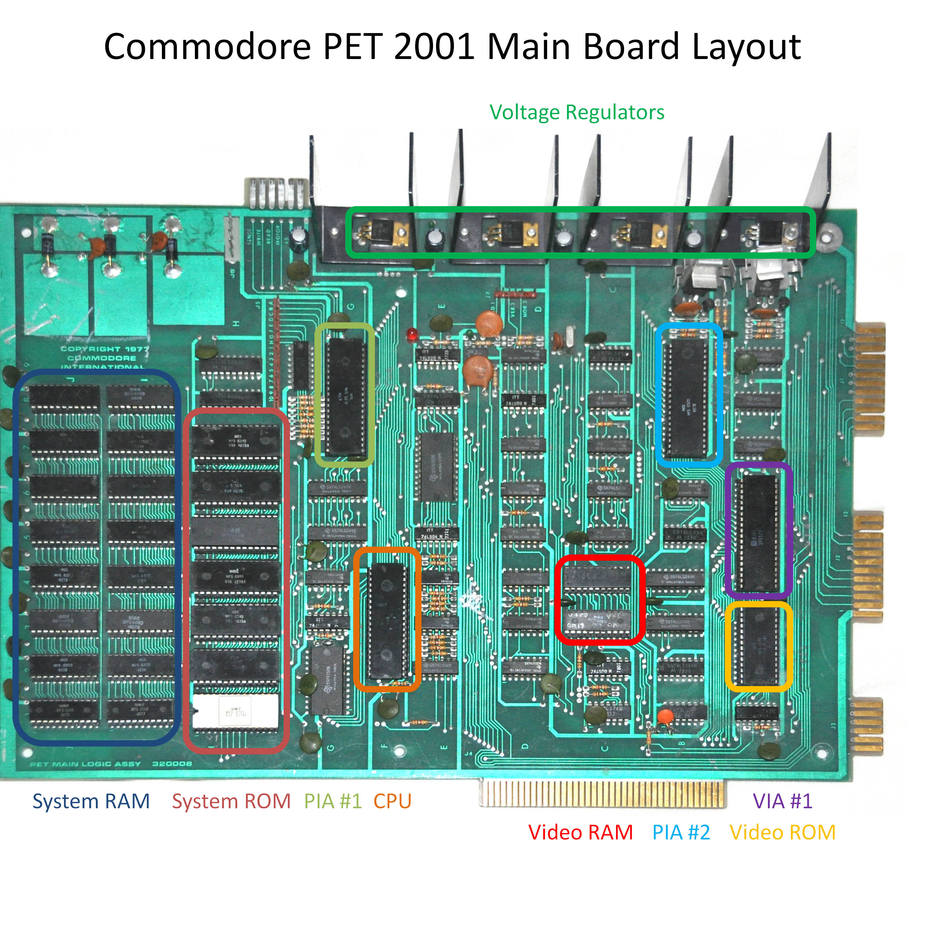
Please refer back to this diagram as needed when reading through this document to figure out where the parts that I am referring to actually are on the motherboard in your PET. Also note that there are numbers going up the left side of the board and there are letters going along the bottom of the board. These letters and numbers form a grid on the board by which components can be identified. For example, the CPU is at F3. This system is used in place of numbering the individual chips (i.e. U1, U2, U3…) and is used by Commodore on all the official schematics. Also note that when I refer to upper / lower / right / left these I am assuming the same motherboard orientation as is shown in the photograph.
Troubleshooting the power supply
Testing the power supply in a PET is (luckily) very easy. Just measure the voltage between the middle pin (ground) and the lower pin (+5V) of each of the four voltage regulators with the PET turned on. Each voltage should be in the range of 4.8 to 5.2V with less then about 50mV of ripple. If they each meet this spec, then the power supply is working fine.
If all the regulator outputs have roughly equal problems (low voltage or excessive ripple) then suspect the large filter capacitor on the chassis, one or more of the rectifier diodes on the board, a shorted regulator or bypass capacitor on the board or the power transformer. Troubleshoot / correct accordingly.
If only one (or two) of the regulator outputs shows excessive ripple or low voltage, then the problem is either a bad regulator or a one of the ICs fed by that regulator has shorted and is loading it down. If such a short has occurred, then the affected IC will quickly become quite hot. Feel each IC in the machine to identify the problem. Remove it and retest the rail. Else, try replacing the regulator. (You can carefully unsolder the output lead (lowest one) and solder a new one in ‘parallel’ to test before replacing it outright.) Replacements are easy to come by as the part is a standard 7805.
Troubleshooting Video Problems
I will define video problems here a problems that result in a corrupted display on a machine that otherwise seems to boot normally, although severe problems with the video circuit can also make it appear as if the machine is not booting or even prevent it from booting. See the next section for booting problems.
First, be sure that your problem is not with the PETs internal monitor. The simplest way to do this is to use one of my Commodore PET Video Mixers to (temporarily) replace it with a standard external composite video monitor. Apple II or Commodore 64 monitors work well for this. If the problem is with the internal monitor, it is most likely due to bad electrolytic capacitors on the monitor board. Test with an ESR meter and replace as necessary. I haven’t ever fixed one of the internal PET monitors, so unfortunately I can’t give more specific hints then that.
Assuming that it is known that the problem lies with the video circuitry in the PET itself, a quick overview of how the system works is in order. The video system consists of two main components: the video ROM and the video RAM. The video ROM contains the sequence of bits required to form the characters seen on the screen while the video RAM keeps track of what character is displayed at each position on the screen. Thus, generally, video problems that affect certain characters or groups of characters independent of their position on the screen are likely to be due to bad video ROM while problems that affect specific screen locations are likely to be due to bad video RAM. Of course, the most common problems are a completely failed ROM or RAM in which case this distinction is not so useful.
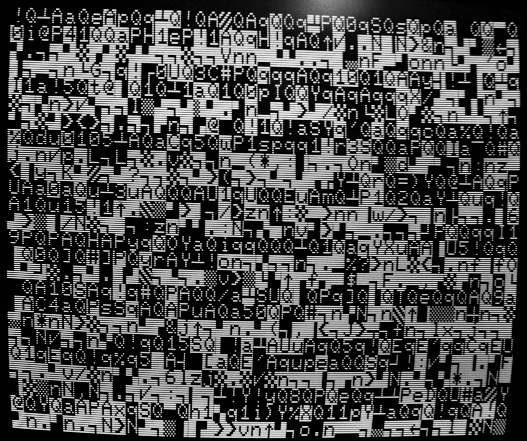
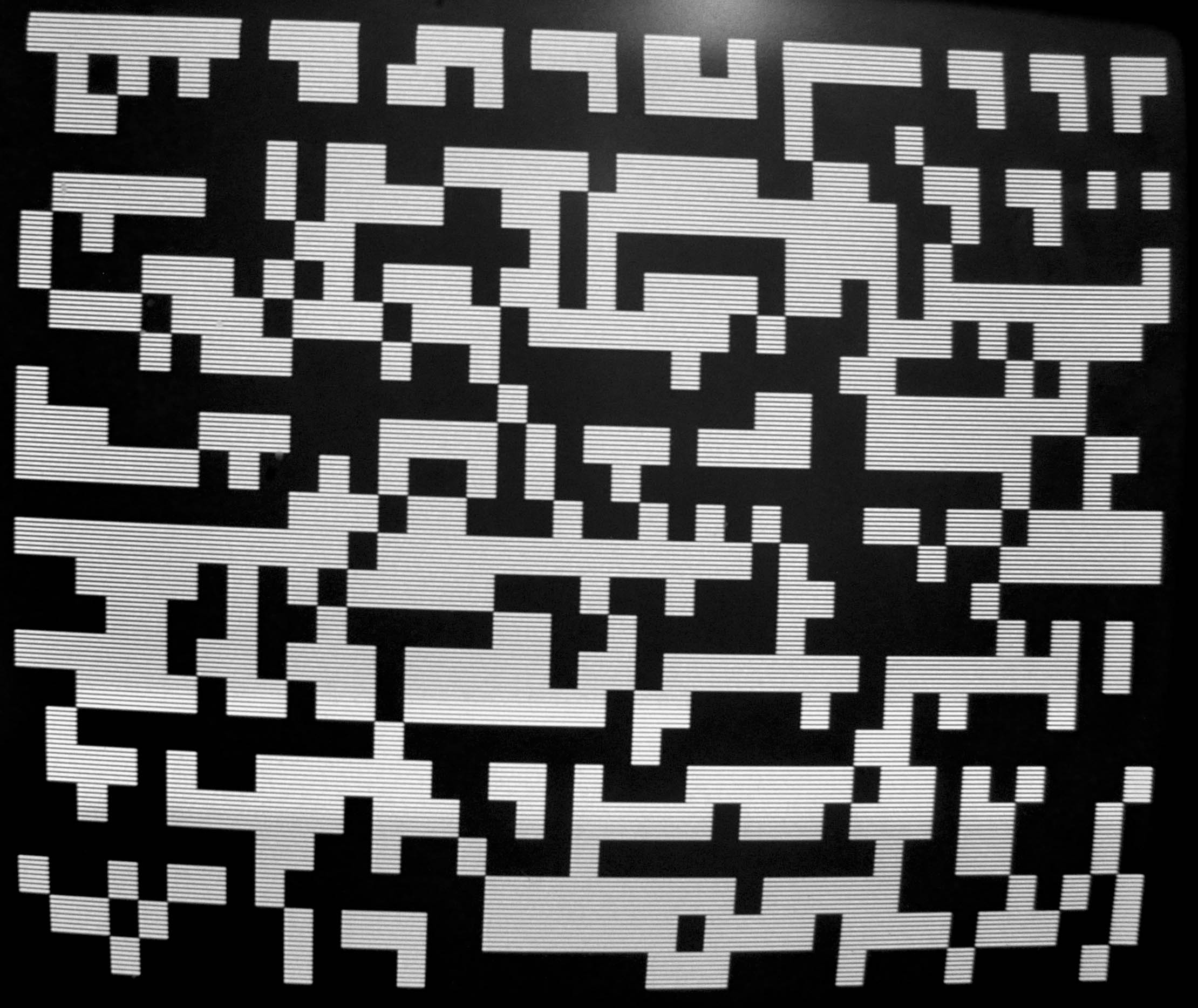
When the PET is first turned on, before the CPU reset a second or so later, the screen should be full of a perfectly random arrangement of characters as shown in the picture below. If you see this, it likely means that the video system is fine. Thus, your goal in troubleshooting the video system should be to achieve that result. Below is a set of photos of common video system failures and their causes.
Normal turn-on screen
This is what you are aiming for.
The same character (usually ‘@’) in each position on the screen
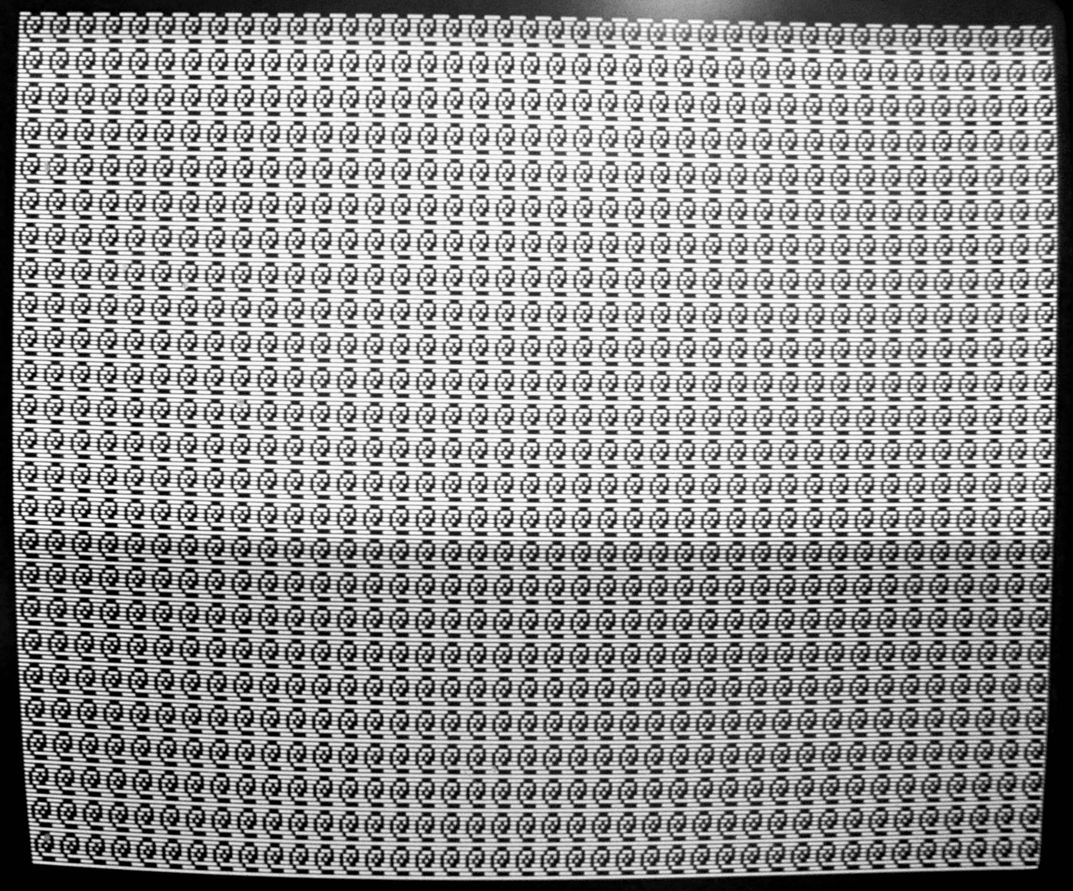
This screen is usually the result of a failed CPU. Because the CPU contains the clock divider circuitry that produces the clock-phases used by the video circuitry, if it is not present the characters stored in the video RAM (random noise) will not be displayed and instead the character represented by the code 0x00 is displayed. Check the CPU carefully for bent or corroded pins, re-seat it a couple time, and if that doesn’t work try a replacement.
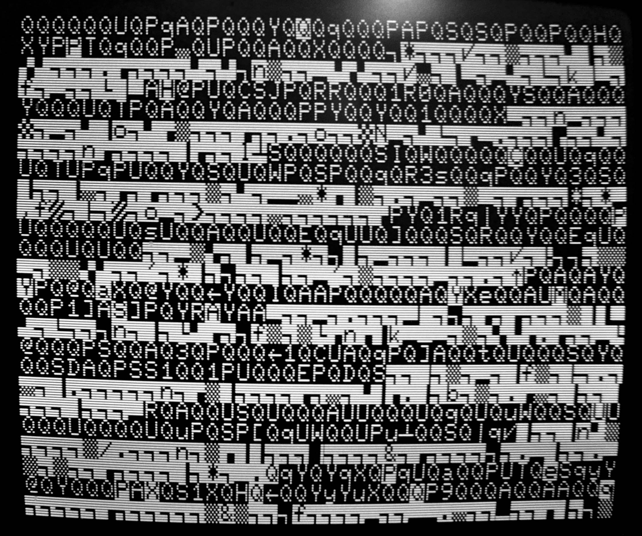
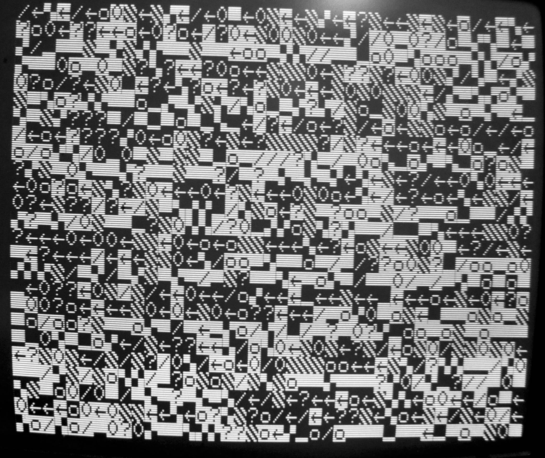
Invalid characters displayed
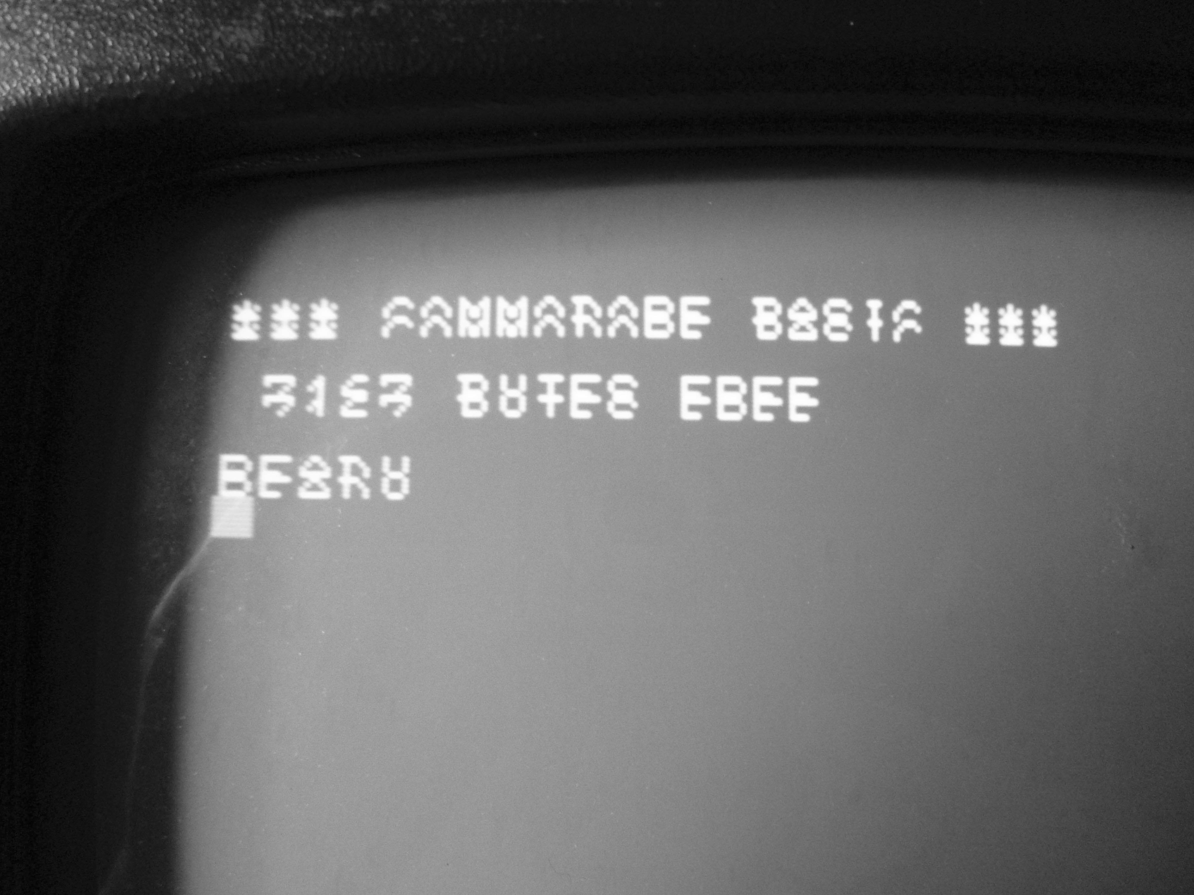

Both of these cases represent bad video ROM. Note that in each case invalid characters are displayed. These pictures are shown for a PET that has booted, but the same effect can be observed on the turn-on screen. Any time you see invalid characters, replace the video ROM. My 6540 ROM adopters are the correct solution for this if you pet uses MPS-6540 type ROM chips. If the turn-on screen looks like random noise, it is possible that the wrong ROM is inserted into the video ROM socket. Be sure the number on the video ROM is 6540-010 for a type 6550 ROM. I don’t what number appears on the 2316B video ROMs.
Finally, the photo below shows the the turn-on screen for the case when the video ROM has been completely removed (or has failed utterly).
Non-random characters are displayed
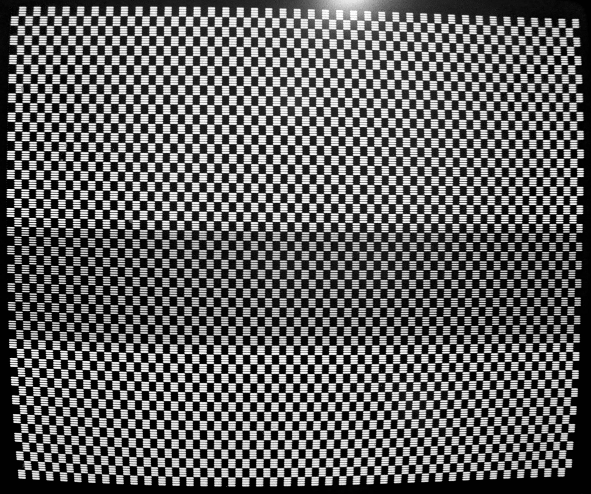
The photo below shows a classic case of bad video RAM in the left video RAM socket. The stripes of identical characters represent stuck bits in the RAM
Here is the same bad RAM chip inserted into the right socket. The pattern still shows non-random patterns, but it is more subtle. Note that a much smaller range of characters are represented then should be.
One of the best tests of video RAM is to observe the startup screen and note how random the collection of characters appears. Good video RAM will show a very random distribution of characters. Failed or failing RAM will usually show patterns as seen in the photos above. If you observe non-random patterns, turn off the computer, replace one of the video chips with one of the main memory chips and turn it back on. Repeat until you have found a pair of RAM chips that produce a uniformly random screen of characters. As explained later, this test also serves to identify bad system RAM chips.
It is worth noting that some 2114 RAM chips, even when good, do not appear to produce perfectly random patterns the first time they are turned on. For those chips, it works better to turn the system on, wait a second or so, turn it off, then turn it back on and observe the turn-on screen for randomness.
Finally, here is a photo showing the turn-on screen for a PET with both video RAM chips removed or completely failed.
Troubleshooting Booting Problems
OK. Now onto what is most arguably the most common problem. Your PET won’t boot. It stays on the random-character screen, or it starts to boot but hangs on a blank screen, or maybe it boots to the point of showing some of the startup text but then hangs. What to do?
The first step is to make sure the power supply and video system is working correctly per the previous sections. Next, try removing and cleaning the pins on all the chips if you haven’t done so already. If neither of those work, read on.
Minimum components needed to boot a PET
When troubleshooting booting problems it is useful to remove all the socketed components that are not necessary. This eliminates the possibility that one of them is prevening the system from booting. The following complement of chips will allow the PET to boot, albeit without a cursor or working keyboard:
Remove:
-All system RAM except for four chips. For systems with 6550 RAM chips, those chips need to be in locations I1, I2, J1, and J2 (bottom most four chips in the board layout picture). For systems with 2114 RAM chips they needs to be in locations I7, I8, J7, and J8 (top most four chips in the board layout picture).
-PIA #1
-PIA #2
In this configuration the system should boot and say that it has 1023 bytes of RAM free. If it does, insert the components one by one until it stops booting, thereby identifying the problem part. If not, your problem could be a bad ROM chip, a bad RAM chip, a bad CPU, a bad VIA, or a problem with some supporting logic chip. The only way I know of to find a bad CPU or VIA is by substitution, and finding a bad supporting logic chip is even harder, requiring troubleshooting with a logic analyzer/oscilloscope and a bit of luck. Luckily, though by far the most common problems are with bad ROM and RAM.
Finding a bad system RAM Chip
If your system boots, then identifying a bad RAM chip is easy. Just use the tables below to find the bad pair of chips, then substitute them one at a time with another system RAM chip until the fault moves, thus determining which of the two is actually bad. Note that the location depends of whether your PET uses MPS-6550 RAM or 2114 RAM.
| Bytes free | Bad 6550 location | Bad 2114 location |
| 1023-2046 | J3 or L3 | J6 or L6 |
| 2047-3070 | J4 or L4 | J5 or L5 |
| 3071-4094 | J5 or L5 | J4 or L4 |
| 4095-5118 | J6 or L6 | J3 or L3 |
| 5119-6142 | J7 or L7 | J2 or L2 |
| 6143-7166 | J8 or L8 | J1 or L1 |
However, if the system will not boot, the best way to find bad RAM chips is to substitute, one at a time, each of the system RAM chips into one of the video RAM sockets (the left one seems to work best), while looking for non-randomness in the turn-on screen as described in the ‘Troubleshooting Video Problems’ section. Of course, be sure to shut off the computer before unplugging or plugging RAM chips. By going through this process, you should be able to sort out the good system RAM from the bad system RAM. Once you have four chips that you are pretty sure are good, put them into the board (see the ‘Minimum components needed to boot a PET’ section above) and see if the system will boot.
Once you have it booting, verify that the ‘bad’ ROM chips are actually bad by substituting them back in and seeing if it still boots. 2114 RAM chips are standard and easy to get, but if you need replacement MPS-6550 RAM chips the only solution I am aware of is my 6550 RAM adapter.
Finding a bad system ROM chip
Finding bad ROM chips is harder then with RAM chips because each ROM chip is programmed differently and thus they cannot be substituted for each other. For this reason, if you suspect bad ROM the first step should be to make sure that all the ROM chips are in their correct sockets. Use the table below for computers with 6540 ROM chips. Sorry, but I don’t have similar information for the 2316 variant but you might be able to figure it out from what is given here.
| Location | Part number on ROM chip |
| H1 | 6540-011 or 6540-019 |
| H2 | 6540-013 |
| H3 | 6540-015 |
| H4 | 6540-016 |
| H5 | 6540-012 |
| H6 | 6540-014 |
| H7 | 6540-018 |
Assuming that all the ROM chips are present and installed in their correct positions, the only way to know for sure if they are good, aside from subsituting them into a working PET, is to use my EPROM Programmer Universal Adapter in conjunction with a Willem EPROM Programmer to read the contents of each ROM and compare them against the ROM images available here. There is another test, which I will describe, but it will only catch a ROM if it fails completely. The test involves substituting the ROMs one at a time in place of the video ROM. When the PET is first turned on, the screen should be full of what looks like random noise (see the picture below.) When performing this test, remove the system RAM to prevent the system from booting. If it is not, the ROM is probably bad. Another test is to use a PETvet to replace all the ROM in the system at once and see if that solves the problem. Of course, even if it does, that still doesn’t tell you which of your original ROM chips is bad. Also be aware that a failed (shorted) ROM (or RAM) chip can prevent the system from booting even with the PETvet installed. Once you have identified a bad ROM, use one of my 6540 ROM adapters to replace it (if you pet uses MPS-6540 type ROM chips.)

Conclusion
I hope this has helped you bring your PET back to life. If not, I am happy to take specific questions and also do repair work on PET 2001 computers. All you need to send me is the motherboard so shipping will not be expensive. Contact me if you are interested. Finally, do be aware that this document is by no means complete or necessarily 100% accurate It simply outlines some useful techniques which I have read about or discovered in the course of my various Commodore PET 2001 projects. I take no responsibility for the results of your attempting to use these techniques.
Hi, I’m french and have no s’ils in electronics… I luckily found à Commodore like yours, power is OK, but first and single screen is with “!”… What can that means ?
Thanks for your first help diagnostic in advance, regards,Stan
Thanks for your comment. The symptoms you describe are generic and could be due to many problems, but are most likely caused by a failed ROM chip. Follow the directions in this post for testing your ROM chips, or contact me through the contact link if you would like to have me repair your PET motherboard. Good luck!
-Matthew
Hi,
I would like to know if there is a risk, with the Commodore PET, that a bad power supply start sending too much voltage and destroy components in its path like it can happen often on a Commodore 64 that is connected on a bad PSU.
Thanks.
Thank you for your question. Let me first explain a bit about the power supply. The Commodore PET uses a very simple linear power supply which consists of a power transformer, rectifier bridge, filter capacitor, and a set of four 78L05 +5V regulator chips. All of these parts except for the transformer and capacitor are on the PET motherboard.
Because of its simplicity, this power supply is very reliable – in fact I do not recommend even replacing the electrolytic filter capacitor unless it is known to be bad because it is overrated and of such high grade. In fact I have never seen one of them fail. In fact, the only part of the PET power supply which I have ever seen trouble with is the 7805 voltage regulators. Occasionally I have had to replace a failed one of those, but when they fail they do not appear to produce any kind of over voltage condition.
To summarize, while it is theoretically possible that a bad power supply could damage other parts of a PET, it is very unlikely. I have never seen this happen nor am I aware of it ever happening.
-Matthew
I am working on my Commodore PET 2001-8 and as I have seen before there seems to be a burn mark on the J8 Molex connector, indicating that something must be heating up.
My system will boot up fine one day and not even turn on the screen the next. I have noticed that the J8 connector is a bit loose and can be moved form right to left. So, I removed the five wires going to the molex and bent the pins out a little, so that they would make a better connection.
Sometimes I do get odd memory counts and sometime I get a full memory count. I do have a good chip tester but I hate pulling them out as they can be difficult to get back in.
Mathew, i have a Pet 2001 which I just started up after being in the shed since doomsday, it came on fine ,the monitor fired up,but all “gobbildy gook” so I pressed a few keys (bad move) screen went blank, the LED lights stay on top one and bottom one of ten,any ideas would be grateful,Thank you Laurie
Thanks for your comment. The original PET 2001-8 is identifiable before it has a chicklet keyboard and the motherboard looks like the one in this article. It only has one LED on the motherboard, so I don’t know what you are referring to with “LED lights stay on top one and bottom”. Can you please elaborate as to what model of PET you have? That said, in general I cannot provide advise in specific cases beyond what is spelled out in this article. If you would like me to repair your PET motherboard, please contact me through the link on this site.
-Matthew
Hi,
I’ve just bought a PET 2001-8C and I see, that the problem is with H7 ROM chip.
I need to get a replacement with ordinary rom.
Can You help? ::)
Thanks for the question. If your PET uses type 6540 ROM chips (you can tell because they have 28 pins and are marked as MPS 6540) then you can use buy one of my adapters. Just search eBay for “6540 ROM Adapter” to purchase. If, on the other hand, you PET uses 2316 ROMs (with only 24 pins) then I don’t have a ready solution. Some other people have made adapters if you look around online.
-Matthew
Hi again.
I get another PET 2001 (from my friend) and I replaced all roms but there is still the same garbage on screen- I replace everything without ram. My roms don’t work with his motheboard.
My friend has other problem with his PET – it’s booting up but the screen text is moved to the left and after a few moments the screen is going shaking and blinked off – on my display is going fine.
Is there any screen adjustement for horizontal phase?
Hi
Thanks for bringing knowledge about the PET to the public. May come in handy in the future.
A fantastic troubleshooting guide. Nicely done.
Thank you so much! And from the man Zimmerman himself!
-Matthew
Hi.
I got a japanese blue pet recently.
The computer boots up but tape drive doesn’t loads.
I got 3 symptoms of it.
1. After loading, it prints ‘?load error’
2. After loading, (with ‘ready’) the blinking cursor doesn’t appear.
3. It just ‘searching forever
I just repaired tape drive few days ago, but nothing changes.
Regards, KNR, from korea.
Sounds like a problem with the tape drive itself or some of the associated circuitry. Sorry, but I can no longer offer PET repair services.
-Matthew
Hi again.
I hooked up another c2n drive to tape port#1, and tried load. And it works very well.
So i thought that the internal tape drive (the original black one) has problem.
So i bring it to audio repair shop in Seoul.
After repair, it still doesn’t load.
But, it records well(?).
(I typed simple code, and saved. After that, i put tape to my tape deck, and pressed play button. The tape plays well(?))
Thanks for your answer. It really helps me.
Regards, KNR, from korea with respect.
Your tape drive may be OK. It is possible one or more of your RAM chips is bad. It may be helpful to try using an external tape drive (any external commodore tape drive will work and are easy to find on eBay). If the problem persists, you have one or more faulty chips on the motherboard. RAM, ROM, one of the 6522’s, or a support logic chip.
Oops sorry. I didn’t read your entire post. Since you have determined for sure that the problem is the tape drive, I would suspect the repair shop is not familiar with this digital cassette drive and missed one or more details. Perhaps try saving on the internal drive, and loading on the external and vise versa to see if the problem is during the save process or the load process. Or save the same program on each drive and compare the files by capturing them as WAV files via a normal cassette player and your audio input jack on your PC.
Excellent article!
I have a very early 2001 8 rescued from my attic. The fuse holder is broken and missing the fuse. Do you know where I can get both from at all please?
Many thanks
Farnell element14 should have the parts. The fuse holder is a standard Littelfuse part. I believe the part number for the whole holder is 03420014H and I don’t believe the cap it sold separately.
-Matthew
I love your troubleshooting guide and find it interesting and useful. Thanks for sharing it!
I’ve owned my PET since 1978. It’s been stored in a clean, dry closet for several years, and now I’m trying to get it working again.
A lot still looks good! For example, I keyed in the following program:
10 FOR I=1 TO 4
20 PRINT I
30 NEXT
RUN
1
2
3
4
SAVE “COUNT”
WRITING COUNT
READY.
NEW
(Rewind tape.)
LOAD “COUNT”
SEARCHING FOR COUNT
FOUND COUNT
LOADING
READY.
RUN
1
2
3
4
So a lot of functionality still exists with this 40-year-old friend. However, when I try to load and run an actual saved program with several lines of code, I get an error:
OUT OF MEMORY IN (LINE #)
I assume that one or more memory chips have gone bad, correct? Do you think it’s RAM, or ROM? What would be my next step?
I really appreciate your help.
Many thanks.
Thanks for the comments. I think it is likely a bad RAM chip, but I can’t say which one. Try swapping them around. Sorry, but I am no longer in business selling parts or performing repairs on PETs and don’t have access to my tools or equipment right now so I can’t be of much more help then that.
-Matthew D’Asaro
Thank you for the article. Can someone tell me what the part in the upper left corner does (on the photo of the motherboard)?
Thank you!
Those are the power rectifier diodes. They convert the AC from the transformer to DC for the motherboard.
-Matthew
Thank you for replying so fast. I have a pet 2001 and it seems like someone soldered some electrical wiring to the diodes in that part. The wires were cut so I don’t think they’re doing something but why would someone do something like that (I have little knowledge about electronics)
Dared turning it on. The fuse was missing so I replaced it and it powered up but the screen gave me some output that ressembled a bad video RAM chips according to your guide.
I replaced it with one of the main ram chips and what do you know it worked!
Ram seemed to be faulty and again thanks to your article I immediately found out which one.
I’m planning on buying the video ram adapter and the main memory ram.
Could you please explain me how to become a genius like you? 🙂 I pride myself to know a lot af computers but I how you can know stuff about the actual chips and all is beyond me..
Thanks a lot for your help (btw most keys (even after cleaning) of the keyboard aren’t working. Any tips?
Thanks a lot and watch out for an order!
I am very glad that my guide worked for you and thank you for your kind words. However, I am no longer in business selling parts or fixing these machines so I can’t sell you replacement memory chips. Try eBay.
-Matthew
Hi, thanks for your information.
I have a blue Pet 2001 that I acquired in 1977.
When aranca appears the full screen with the random characters. After a few seconds they disappear and the screen appears in black, without any message.
That is, the start information of “… 7167 Bytes Free …”
Can you help me? Thank you. Joan
Sounds like bad RAM or ROM. Sorry, but I can’t be of much more help than that. I am no longer selling parts or performing repairs.
-Matthew
Dear Matthew,
my PET 2001 shows an image on the screen but it is compressed to 1 third in the middle of the screen so the letters look like lines. Do you have any idea if I have to look for monitor problem or something in the motherboard?
All voltages are correct and steady in power regulators and chips.
If the image is compressed you have a monitor problem. If the characters are malformed you have a video RAM or ROM problem. Sorry, but I can’t be of much more help than that. I am no longer selling parts or performing repairs.
-Matthew
Love your work here…so sorry to hear that you are no longer selling parts, etc…
I have been tinkering on a 2001-8 and suddenly, some of the BASIC commands such RUN are reported as a ?SYNTAX ERROR and when I load a small program that loaded just yesterday, it says it loaded, but of course will not run because the RUN command is no longer recognized, but listing the program shows…gasp…nothing.
I was in the midst of re-seating some of the chips when at first the screen went blank and I was fretting, but then found that the first ROM chip on the right needed to be sitting a bit higher on the bottom side of the socket, towards the front of the machine, and then I at least got the screen back.
I am going to get some very fine contact cleaner or some sort as I am pretty sure the first two rom sockets and the first 4 ram sockets were contaminated…by what appears to be chocolate…that was one likely liquid, but not any more…and I can not imagine that such contamination would be a good thing for any of the connections…might also be time to replace some of the sockets or perhaps put the chips in better sockets that can better make contact through the residue, but soon, I hope the hardened chocolate slime is gone with the application of the correct contact cleaner…not sure what that is as of yet.
I hope you are doing well at what you are doing, and sorry that you are no longer doing the PET things…but it is good of you to keep answering questions…I wish you well…very well indeed!
…David Bradley
Thanks for the compliments. Hopefully, I will eventually get the time to do PET stuff again. Anyway, the problem you describe with it not running programs is most likely bad RAM, but it could be bad ROM as well. Make sure everything is clean first. In cases of massive contamination (like it sounds like you have) I wash the board in hot soapy water and then bake it in an over at 60C for an hour. Works marvelously.
-Matthew D’Asaro
Hi – I have a PET 2001 with the ‘chiclet’ keyboard. It boots and tells me that there’s 7167 bytes of RAM free (it’s the original 320008 version with 6550’s and 6540’s). The problem is, it doesn’t respond to any keystrokes – nothing happens. I see that the inputs to G9 are cycling but all it’s output lines are low (but it’s an open-collector chip, so they shouldn’t change voltage anyway). That suggests to me that the CPU is awake and running OK. Watching some of the KINx lines at the keyboard, I see them pulse when I press certain keys – this suggests that the keyboard is being read. But somehow, the CPU is not aware of the keystrokes. Might you have any suggestions?
Probably a bad 6520 PIA in position G8. Try swapping it with the one in position B8 and see if that fixes it. If this isn’t it, the only other real possibility is the 74LS145 at position G9. However, I have never seen one of those fail, so I would be sure I have a good PIA and keyboard before trying to unsolder it.
-Matthew
Greetings! Great site/info. Thank you for that! I have a PET 2001 in my shop that is blowing fuses. One minute it worked fine then the fuse blew. Our customer bought some fuses at the local h/w store but they are 1.5a and they just blow out as I believe that it require a slo-blo 1.6a. My question is, what is the part number of a compatible fuse for this unit? Also, am I correct on the fuse spec.?
Also, I’ve gone over the unit very carefully looking for charring or other damage/shorting on the logic-board and found that one of the voltage rectifiers is cracked and the other 2 at their solder points look like they may have heated up enough to cause the solder to bubble out some flux.
Could this have caused the blown fuse or is this because of something before the fuse blew? Chicken or egg first, I guess 🙂 ?
Thanks a bunch in advance!
-Steve
Yes, blown diodes would cause the problem you are seeing. However, the diodes likely blew because of a shorted voltage regulator (7405) or a shorted capacitor. Check these before replacing the diodes. Either a 1.5A or a 1.6A slow blow fuse will be fine.
-Matthew D’Asaro
hello
my pet boots normally but without sound
i have the 2001 pet 32k
thanks
I don’t wok on the later 32K PETs and I don’t know why it wouldn’t produce sound. The original 4K/8K PETs didn’t have a speaker.
-Matthew
Hello
Pet 2001-8B
It turns on, a machine code appears. After a few hours of inactivity, a flashing cursor appears, but when you click on the keyboard, it immediately freezes and shows the wrong characters that you press.
Help me please.
Could be lots of things. Most likely bad RAM or ROM. Follow the instructions in this article.
-Matthew
Hi matthew
can you repar a pet 2001 ?
i m from france.
thank you
Sorry, I am not doing repairs on these right now. I am too busy with my day job. However, I hope to have more time again by the end of the year. I will make an announcement on the main page when I am back in business.
Thanks for the guide. I have a very early board with 6550 RAMs. At first it wouldn’t do anything but show random characters on screen. I found that one of the 5V rails was bad. When I replaced the 7805 the system booted showing 4096 bytes of free RAM. I tested all of the keys and only some of them worked. After a good clean-up I got most of them to work but on row 4, every other key did not work, this include the Enter key. I found that all the keys had a common line. I made sure the connection was good to the motherboard. Since it was I decided to swap the 6520s. This produced no effect except now none of the keys worked. I swapped the 6520s back but there was no change. None of the keys work now.
Meanwhile I decided to find the bad RAM as described above. The end result is the screen now shows 7167 bytes free. I can only assume that it was an oxide issue that cleared up by multiple removal/insertion cycles.
Does anyone have any suggestions about the keyboard? Are my PIAs bad? Where can I get replacement parts?
It is most likely a bad 74LS145 at position G9.
-Matthew
Hi Matthew,
great work here!
Maybe you can give me a tip for a Problem with my PET 2001 (Micky Mouse Keys). I have found 2 dead RAM-chips (6550) an replaced them with working ones. Now Basic showes 7167 Bytes free, but only if PIA #2 is not in place. If I put it in place, the boot stocks at the turne on screen, no matter witch of the both Chips are in Position 1 or 2. Furthermore ther is a problem loading Programs. Ther are two different reactions:
1.
LOAD
PRESS PLAY ON TAPE 1
SEARCHING
FOUND **** (the correct program)
LOADING
?LOADING ERROR
READY
2.
1.
LOAD
PRESS PLAY ON TAPE 1
SEARCHING
FOUND **** (the correct program)
LOADING
READY.
[no cursor, no input possible]
with best regards
Chris
Yikes. This sounds like a tricky one. Don’t worry about program loading until you have the PIA issue figured out – that is the more telling clue. My first inclination is to suspect a bad PIA, but you already ruled that out by swapping them. The next thing to try is to boot the system with the minimum number of RAM chips (4 as I recall) needed to boot it and see if it still exhibits the PIA symptom – that will rule out one of the RAM chips being the problem. Once that is ruled out, you are down to a bad ROM chip or some support chip being bad. If you have a PETVET or similar you can troubleshoot by virtually “replacing” the ROM with external ROM using that device.
-Matthew
Hey Matthew, I highly appreciate you still responding to the comments you get here. You dont see that too often.
I bought a PET that displays only a single “#” when turned on. Do you by any chance know why this happens? Thanks a lot for any input, i have found nothing at all so far.
I have to ask, what happened to J1 or L1 and J2 or L2 on your Bytes free table?
I forgot to ask, what controls the memory bus on the 2001-8 PET???
Today while booting up Iwas consistently getting 4095 bytes free. So I started be removing J6/L6 then J5/L5 and J7/L7 then J8/L8 and J4/L4 and all tested good in my Backbit Chip Tester Pro V2
I will go ahead and test the remaining chips and reseat them all, as that may help.