Cleaning the encoders in Agilent 33220A Function Generators
Do you have an Agilent 33220A function generator? If so, you may well have experienced an annoying problem where the control knob does not operate smoothly – the number on the display doesn’t change when the knob is turned, changes erratically, or even changes in the wrong direction! Well, this is actually a very easy fix if you follow the steps outlined below.
Most of the test equipment repair articles on this site are intended for technicians and engineers with fairly advanced skills. They demand advanced troubleshooting, surface mount soldering, reverse engineering, or other skills that can take years to master. However, this article is an exception. Anyone comfortable with a screwdriver should be able to follow these steps and repair their 33220A, saving hundreds or thousands of dollars in the process. For reference, an example of the Agilent 33220A 20MHz function generator is shown in Figure 1 below. These steps should also work with other generators in this same series such as the Agilent 33250A 80MHz function generator and the same idea should work with a wide variety of other instruments utilizing similar encoders.
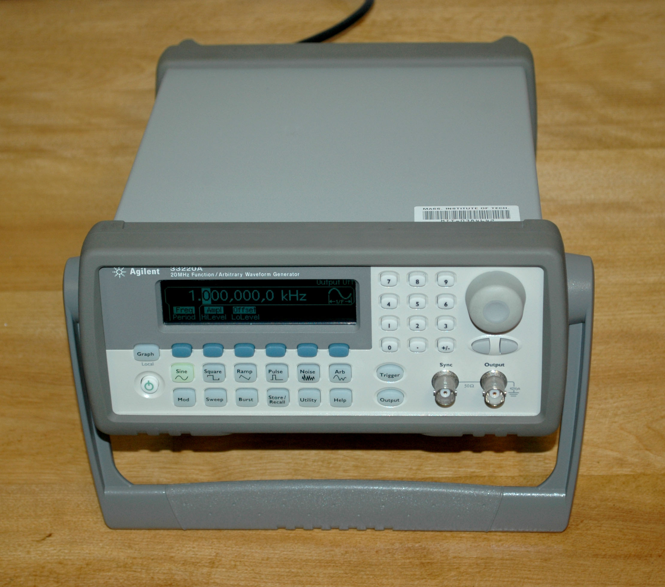
Figure 1: Agilent 33220A 20MHz Function Generator
Before you begin, you will need:
A T20 Torx screwdriver – I recommend a Wiha® 36278. Order here.
Caig® DeoxIT FaderGrease #DFG-213-8G. Order here.
A small flatblade screwdriver such as a Wiha® 26040. Order here.
At least 90% isopropyl (rubbing) alcohol. You can buy this from your local drugstore.
Cotton swabs. Again, buy from a drugstore.
Toothpicksfor applying the FaderGrease. Again, any drugstore.
Step 1 – Remove the handle
The first step is to remove the handle from the instrument. To do this, pull out firmly on the handle where it is attached to the case, then rotate it until it is facing up as shown in Figure 2. With the handle in this position it can be removed by pulling it further out from the instrument and lifting up. The arrows in Figure 2 indicate where to pull.
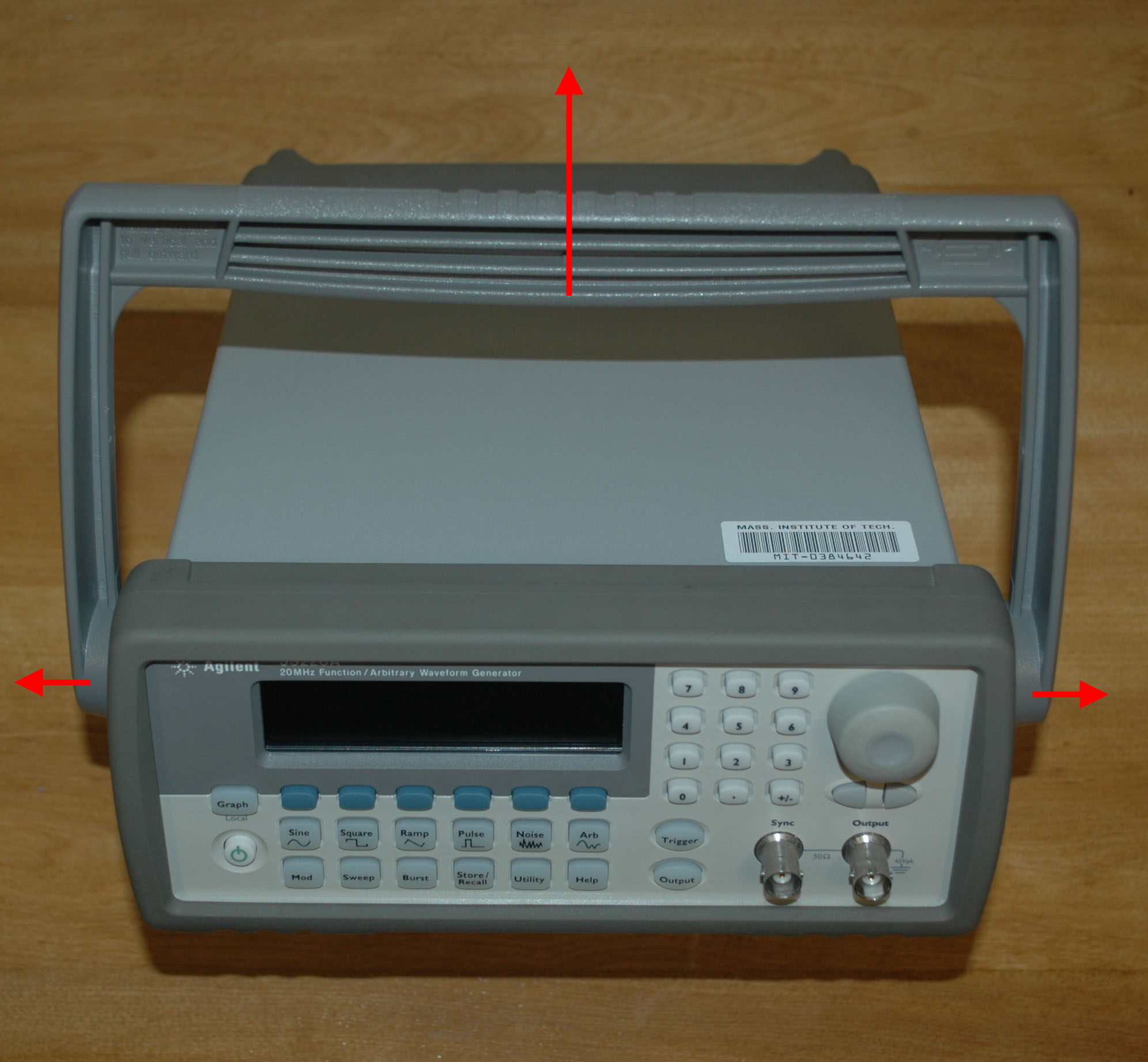
Figure 2: Remove the handle by rotating it into the position shown and then pulling in the directions of the arrows.
Step 2 – Remove the case
To remove the case, use the T20 torx screwdriver to the remove the two screws in the back of the instrument, then slide the case off the back of the unit. See Figures 3 and 4.
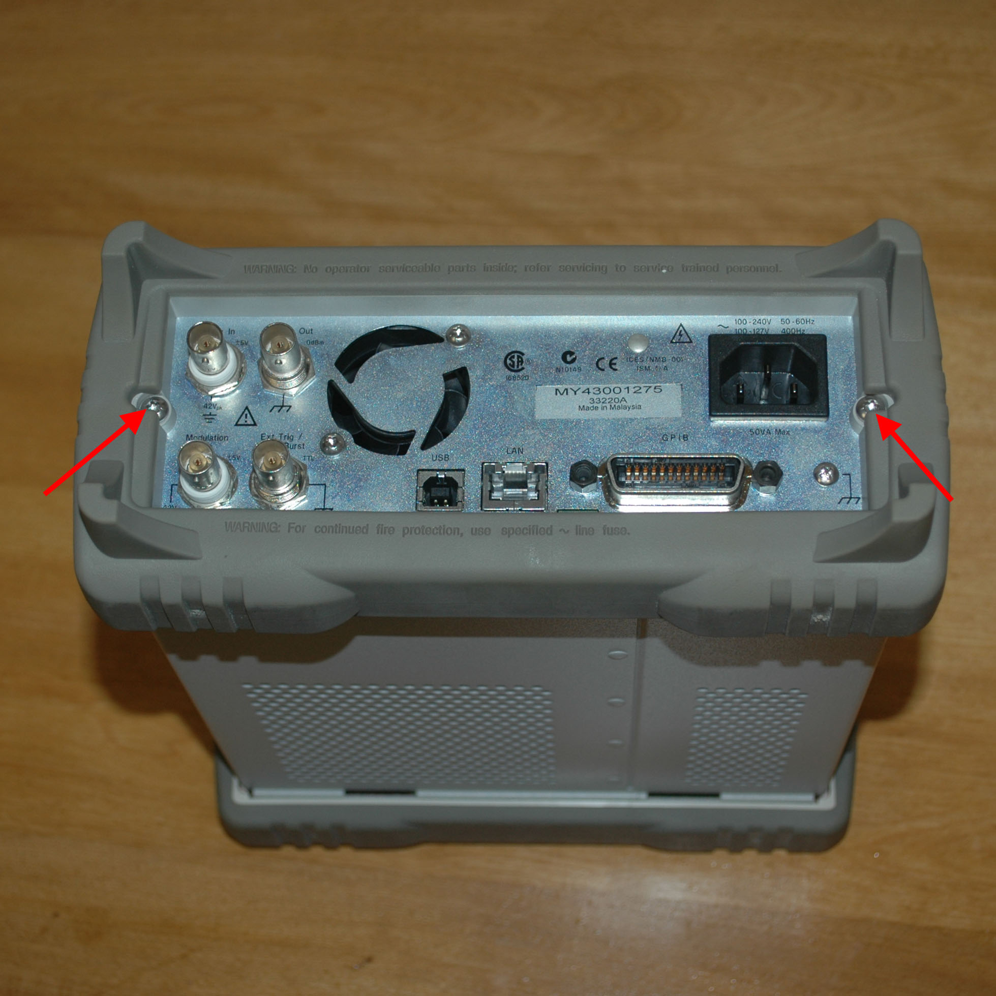
Figure 3: Remove the two T20 Torx screws indicated by the red arrows

Figure 4: Remove the case by sliding it in the direction indicated by the red arrow.
Step 3: Remove the internal shield
After removing the outer case, the internal shield needs to be removed to expose the mainboard. Remove the two T20 Torx screws indicated by the red arrows in Figure 5, then lift the shield off of the instrument. It will still be attached by wires. Do not attempt to disconnect them, just lay the shield assembly to the side of the instrument as shown in Figure 6.
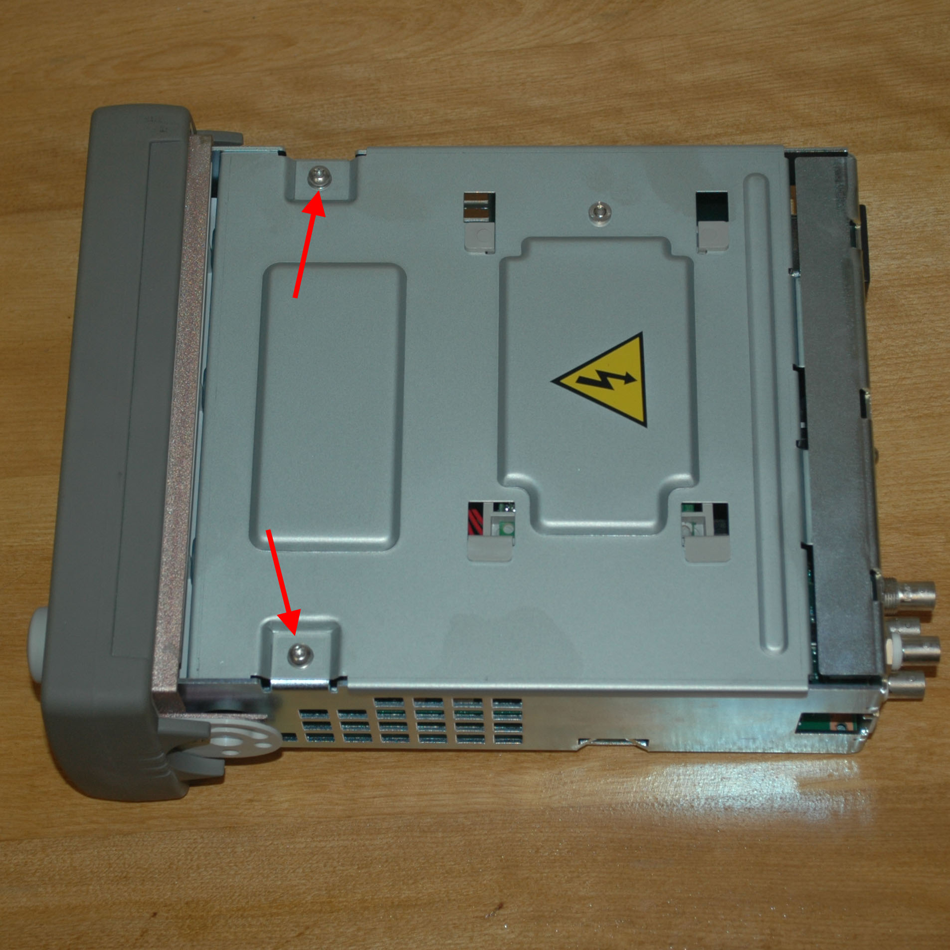
Figure 5: Remove the two T20 Torx screws indicated by the red arrows

Figure 6: Set the shield assembly down by the side of the instrument as shown. The red arrow indicates the location of ribbon cable J201 which should be removed by pulling it straight up from the main board.
Step 4 – Remove the front panel assembly
Next you will need to remove the front panel assembly. First disconnect ribbon cable J201 from the mainboard by pulling it straight up. J201 is identified by a red arrow in Figure 6 above. With J201 disconnected, remove the two T20 Torx screws indicated by red arrows in Figure 7 below. Then, squeeze the two sides of the frame together and pull the front panel straight out to remove it. See Figure 8.
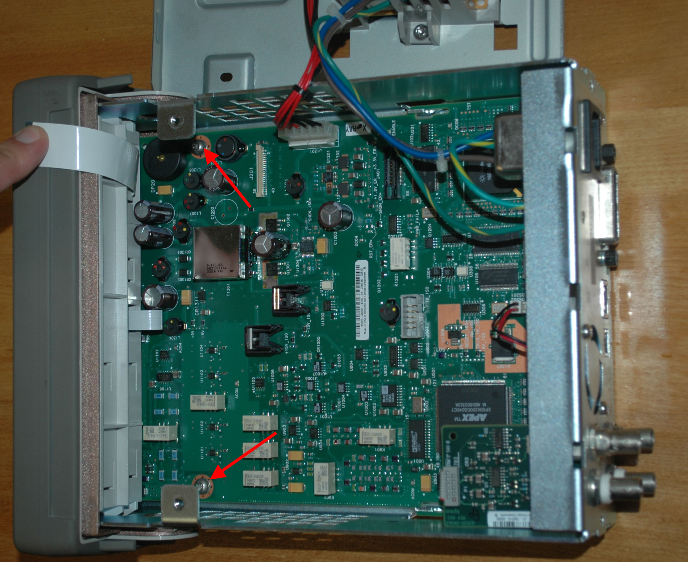
Figure 7: Remove the two T20 Torx screws indicated by the red arrows
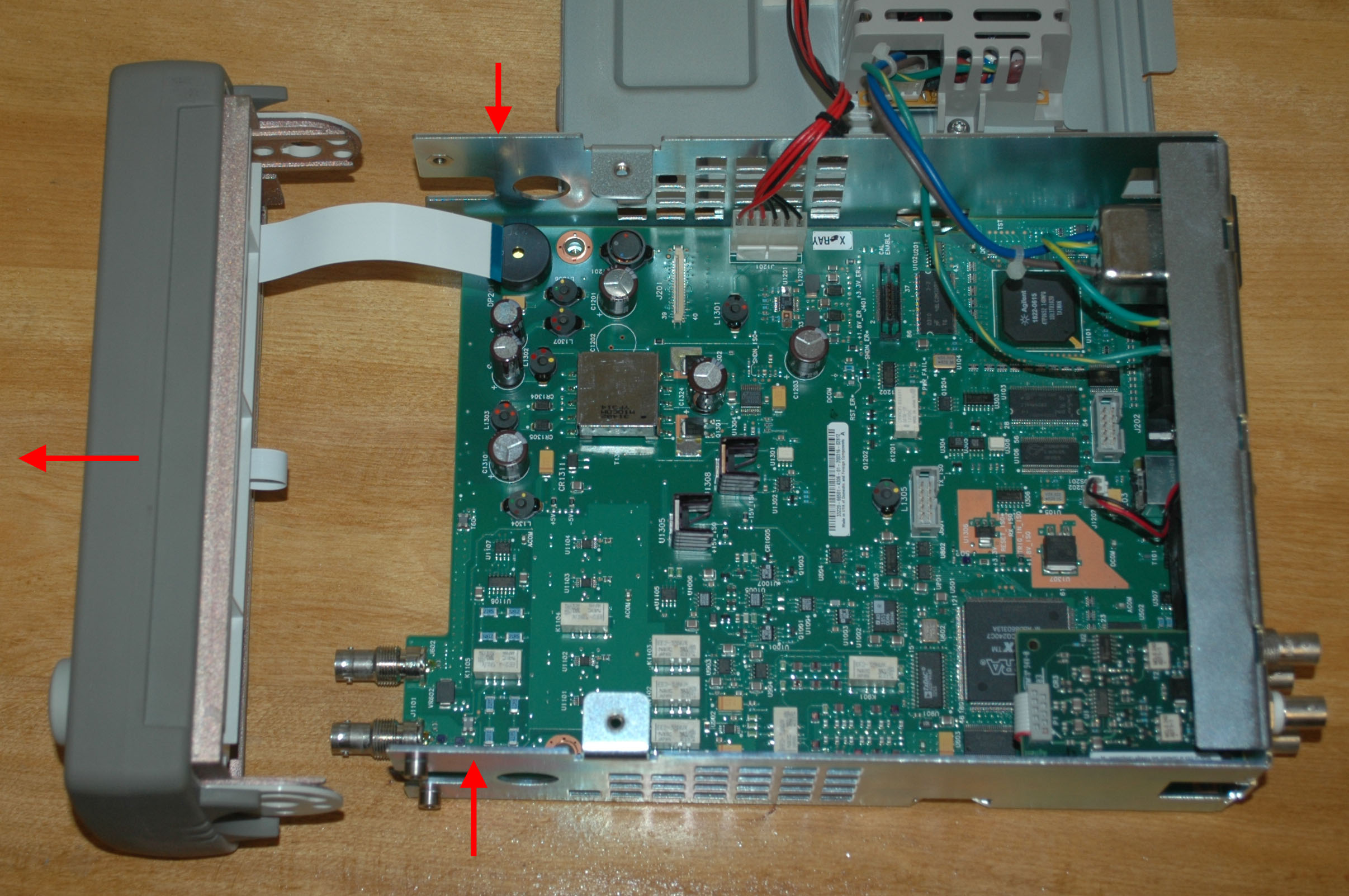
Figure 8: Remove the front panel by compressing the frame as indicated by the two vertical red arrows, then pull the front panel in the direction of the horizontal red arrow to free it.
Step 5 – Disassemble the front panel
The first step in disassembling the front panel is removing the plastic board retainer. Loosen the T20 Torx screw indicated by the red arrow in Figure 9, then remove the retainer by lifting it straight up. Note that the screw is captive and need not be removed from the retainer after loosening. Take care not to catch the ribbon cables on the retainer as you free it.
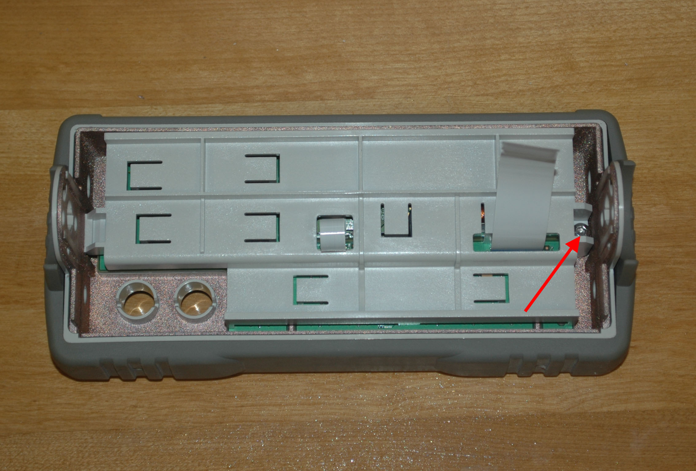
Figure 9: Loosen the T20 Torx screw indicated by the red arrow.
With the retainer removed, the next step is to remove the knob. Turn the front panel over and remove the knob by pulling it firmly straight out from the panel. Then turn the panel back over and disconnect J102 and J103 by pulling them straight out of the front panel board. Figure 10 below indicates the location of these connectors.
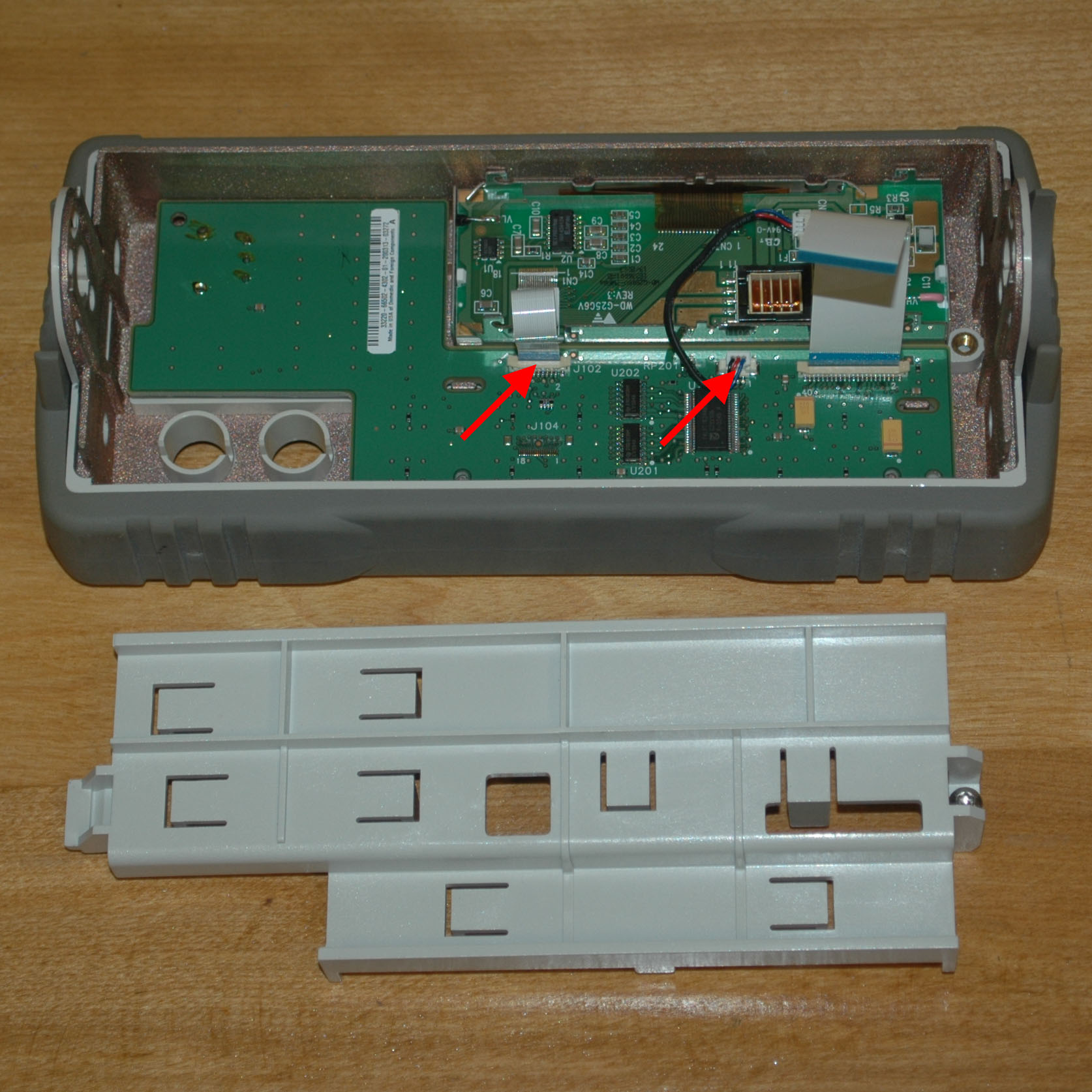
Figure 10: Remove connectors J102 and J103, indicated by the red arrows, by pulling them straight out of the front panel board.
With these steps completed, you can now lift the front panel board out of the panel. Figure 11 below shows this board removed.
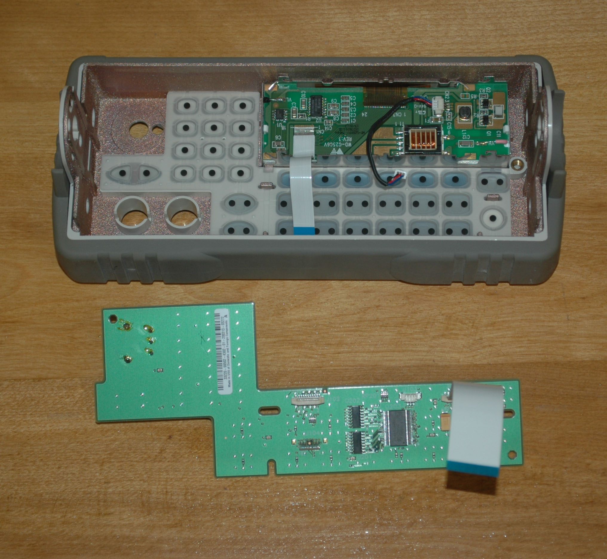
Figure 11: Front panel board removed.
Step 6 – Dismantle, clean, and lubricate the encoder.
Finally, the generator is disassembled to the point that the actual repair can be performed. Using the small flat blade screwdriver, bend the four tabs holding the encoder together away from the encoder body as indicated by the red arrows in Figure 12. When complete, the tabs should look like Figure 13.
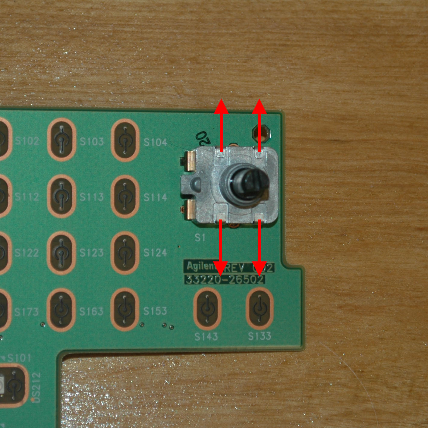
Figure 12: Bend the tabs away from the encoder body as shown by the red arrows.

Figure 13: With the tabs properly bent, the encoder should look as shown.
With the encoder tabs bent as shown, remove the body of the encoder by pulling the shaft away from the board. Turn the encoder body over and clean the points indicated in Figure 14 of all dried grease using isopropyl alcohol and cotton swabs. Be careful not to bend the delicate encoder contacts. On the other hand, the encoder wheel should be thoroughly and somewhat aggressively cleaned to rid it of all dried grease. If you do bend a contact, carefully straighten it again with the flatblade screwdriver or a toothpick. The contacts, when properly bent should make firm contact with the encoder wheel. With all the old grease removed, liberally apply the DeoxIT FaderGrease to the contacts and encoder wheel. I recommend using a toothpick for precise application. Do not apply the grease with a cotton swab as cotton fibers will contaminate it and may cause intermittent operation.
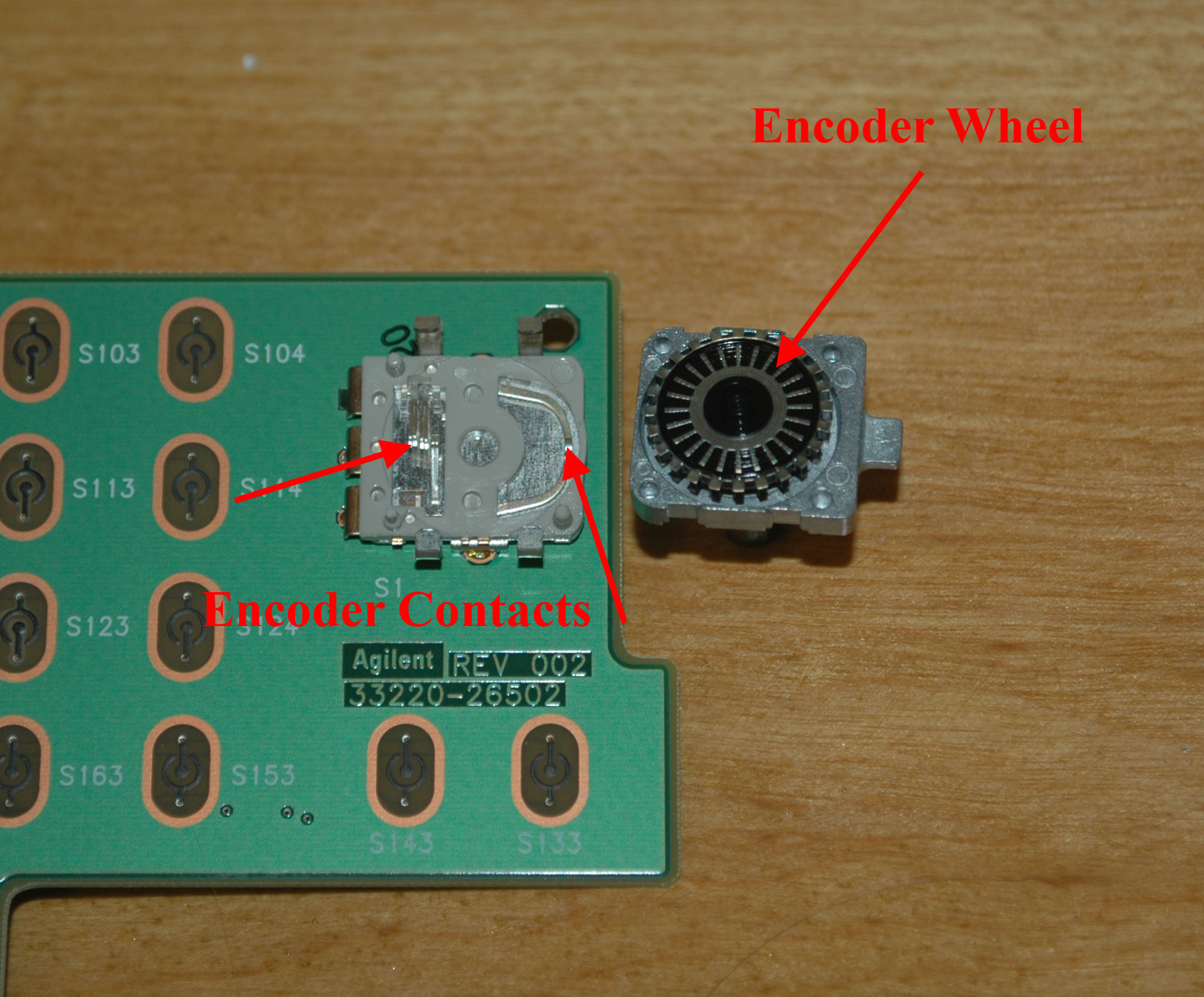
Figure 14: Clean and lubricate the points indicated by the red arrows.
Step 7 – Reassembly
With the encoder thus repaired, the entire generator can be reassembled by following Steps 1-6 in reverse order. Of special note in this process is properly reconnecting the ribbon cable connectors, J102 on the front panel board and J201 on the main board. To reconnect this style of connector, first open the connector by pulling up on it as shown in Figure 15. With the connector open, insert the ribbon cable, and then close it by pushing on it as shown in Figure 16. It is very important that the ribbon cable be completely inserted into the connector before it is firmly pushed closed to assure a good contact!

Figure 15: Before inserting the ribbon cable, open the connector by pulling in the locations indicated by the red arrows.
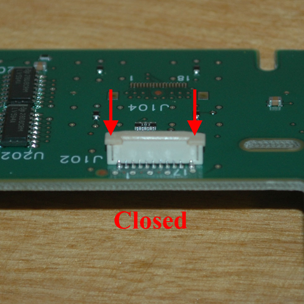
Figure 16: After inserting the ribbon cable, close the connector by pushing in the locations indicated by the red arrows.
Concluding Remarks
Although this process may seem complicated, it is actually quite quick with a bit of practice. If it is any indication, I can do one of these in about 15 minutes. With heavy use the process may have to be repeated every few years, but the DeoxIT FaderGrease should last longer in this application then the original grease. For other problems with this generator, the Agilent 33220A service manual is actually quite good and contains a complete parts list and schematics. Quite a rarity for any piece of test equipment this new. Good luck and have fun!
-Matthew D’Asaro
One trick I want to share with Agilent/HP’s often erratic encoders (on other oscilloscopes as well): rotate it many times in both directions fixed more than a couple dozen encoders for me without fail.
I did it by hand for the first few times, but I got lazy and replaced my fingers with the keyless chuck of my electric screwdriver. Works like wonder because it needs around 100+ turns to make it good as new. You’ll see the response gradually improve as you exercise the encoders.
Thanks for the suggestion! That certainly sounds like a simple thing to try before having to disassemble the whole instrument.
-Matthew
I’d like to know about the ordering code of that encoder?
Thanks for the message, but I have no idea what the part number of the encoders is or if they are even available as a generic (non-custom) part. I have never needed to replace one as I have always been able to fix them.
-Matthew D’Asaro
I ordered a new encoder for a 33220A using the part number 0960-2545 “Rotary Encoder – insulated shaft”
(Please excuse by English….) Hoi Wong, Thanks for the tip!!! This worked quite well with a little help. I first used my cordless drill and a foam pad that i placed between the drill chuck and the 33120A knob (To avoid damage). After spinning in both directions few minutes (Forward / reverse) the job was 75% done but still erratic.
I decided to remove the knob by gently pulling it out. the I placed the 33120A on a vertical position. (Face up) I sprayed “Plastic safe, Electronic parts cleaner / degreaser” ( The brand the I used is Asalco Contact 2000″ To avoid spraying everywhere else than into the encoder itself, I needed something like a funnel that would guide and help the liquid to follow the encoder shaft and go into it. I used a 1/4 inch diameter X about 3/4″ long shrink tubing that I placed over the encoder shaft. That piece of Heat shrink tubing was going to be used as a funnel / guide. Using the straw that was included with the contact cleaner can, I gently sprayed / filled the tubing that was placed around the encoder shaft . The liquid had no other choice that to go into the encoder. Than I put the knob back in place and used use the cordless drill again has I did the first time! 100% success without any dismantling! I hope this will help other people