Designing replacements for the hybird ICs used in the Akai VT-100 Video Recorder
The Akai VT-100, introduced in 1969, is one of the first ‘portable’ video recorders. It is unique in that it records on 1/4″ tape while most early recorders used 1/2″ tape. This, combined with very cleaver packaging and highly integrated (for the day) electronics allowed it to be smaller and lighter then the competition. However, these machines have not stood the test of time well. The rubber rollers and belts fail, the heads rapidly wore out, and the early hybird-ICs that Akai used have proved very unreliable. This, combined with the fact that the tapes from these machines often would only play back well in the machine that recorded them make it quite challenging to transfer old recordings.
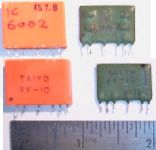
Enter Michele who posted on antiqueradios.com with plans to restore one of these beasts back to working order. After much troubleshooting (and many posts) it was eventually determined that some of the flip-flop hybrid ICs (shown below) used in the sync circuit had failed.
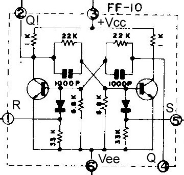
With no other reasonable source for a replacement, I set about to create reproductions. Luckily, the original service manual contained a schematic of the internals of the part, so no reverse-engineering was needed. I annotated the circuit with the logical function of each pin and set to work laying out a replacement.
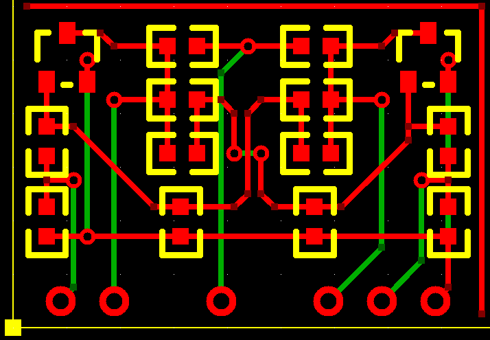
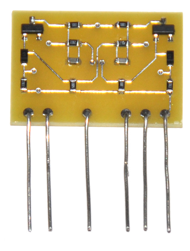
A picture of the layout is below. Since the boards were small I will included them on a larger PCB order at negligible additional cost. The board is the same size as the original part – 7/8″ x 5/8″ so it can be shaved down to fit inside of the orange package, or dipped in it green paint to make it look just like the others.
Parts List:
Transistors: MMBT2222A
Diodes: CD0603-S01575
Resistors: Standard 0603 SMT. The values may have to be tweaked to get the bias point right for the transistors but they should be close to the schematic.
Capacitors: Standard 0603 SMT multilayer ceramic.
Board Image:
When I received the boards I populated them and it worked on the first try. I was amazed – nothing is that easy.
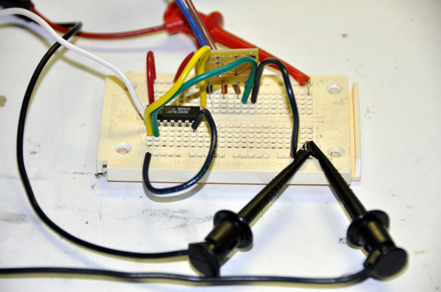
Above is the breadboard that I used for the test. The chip is a 74LS04 inverter which is there so that I can make S and R always be in opposite states. After a quick static test to verify that the circuit retains its state, I applied a square-wave from my new (as of today) HP 8111A function generator to R and to the inverter input with the output of the inverter connected to S. I then connected one channel of the oscilloscope to Q and the other to Q!. With the function generator set to 10KHz and the oscilloscope set to 50us/div I get the following waveform.

I set the oscilloscope to 2us/div and measured the rise-time to be about ~2uS. Below is a picture of that measurement.

This all looked O.K. to me, but the only true test was to be how it performs in the circuit.
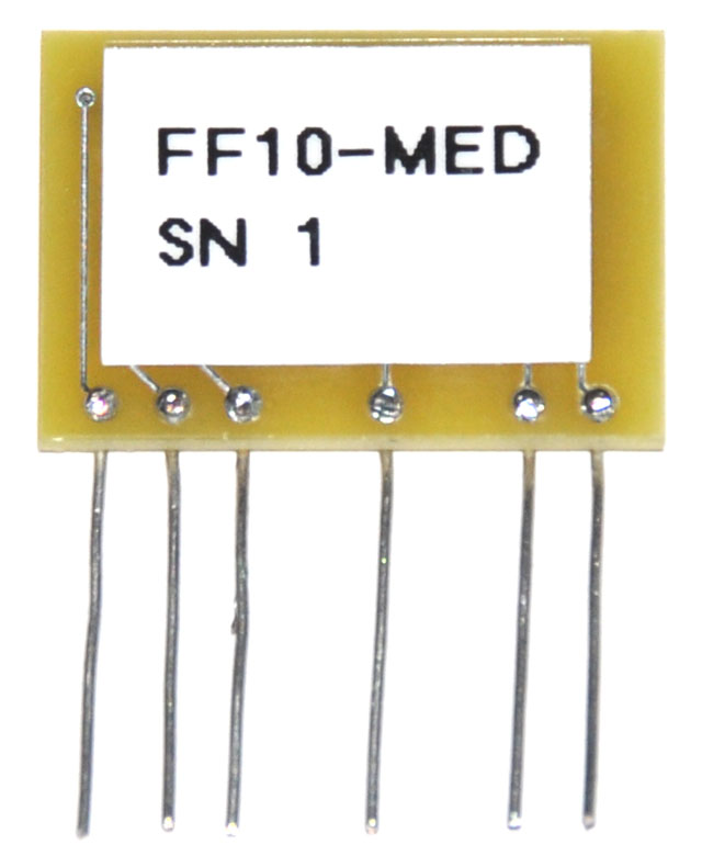
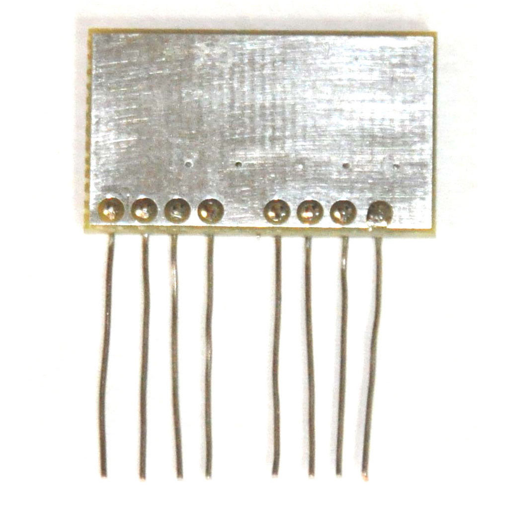
Here are pictures of the front and back of the finished product.
I shipped the parts of to Michele and I think she was happy with them:
holy moly!!! Are you kidding me? That has to be the most amazing piece of work I’ve ever seen. I’m serious – that’s really incredible. You now officially have my nomination for ARF Member of the Year.
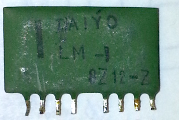
That was not quite the end of the story however. As the project continued, there also came a need for replacement video amplifier modules, part number LM1:
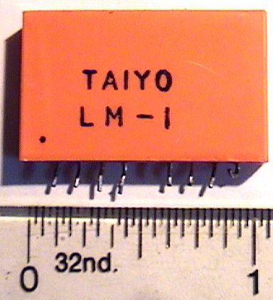
Again the schematic was available so it wasn’t too hard to get going:
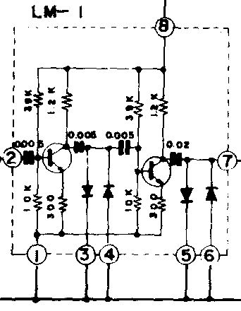
I first did a simulation to verify that I could achieve the needed 2MHz video bandwidth using common MMBT3904 transistors. The simulation showed a gain of 20dB and a 3dB bandwidth of about 5MHz so I proceeded to lay out boards for them.
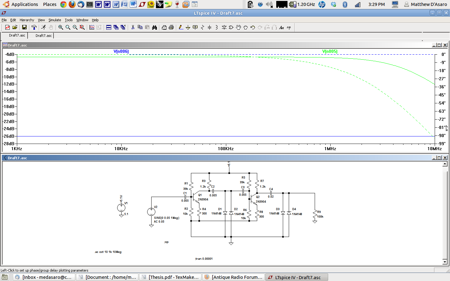
When I got the boards back, the first one seemed to work perfectly on the first try. It has a gain of approximately 20dB into a high impedance load and provides a 3dB frequency of 4.2 MHz, also into a high impedance load. It is pictured below:
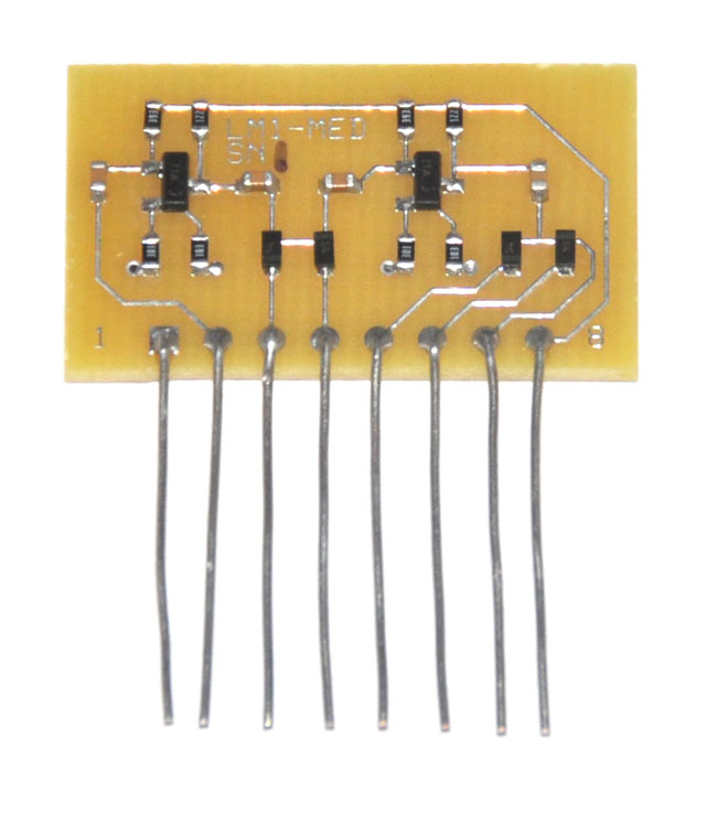
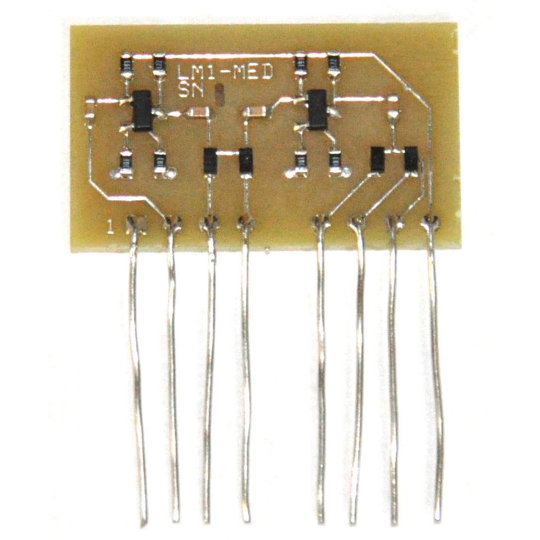
When Michele put it in the VT-100, the video quality was indistinguishable from the original. Unfortunately, there was a small problem. I hadn’t gotten the lead spacing quite right so it wouldn’t sit flush into the board:

This was luckily an easy fix, and the final version (pictured below) fits perfectly.
Many thanks to Michele for all her work testing my parts.. The reproduction FF10 and LM1 are available for sale at the links below:
-Matthew
Note that this post has been modified from:
http://antiqueradios.com/forums/viewtopic.php?f=3&t=161384&start=40
The publication date has been modified to reflect the original posting date.
February 2, 2016
Dear Mr. D’Asario, D’Asario Designs:
My name is Assoc. Prof. emeritus Mitsuru Kataoka, UCLA Arts. I started the UCLA Dickson Video Laboratory in 1970, (not having any technical knowhow) with a grant of 8 Akai VT-100 portapaks, 2 Akai VT-110 portapaks and 1 VT-700 console provided by Mr. Akai, himself in response to my proposal to create a video program of courses for artists, designers, architects, anthropologists, and historians.
Dickson Video was accessible to a wide range of faculty and students including UCLA Anthropology Prof. John G. Kennedy and Design Prof. John Neuhart beginning in 1972.
Kennedy and Neuhart took one of the Akai VT-100 portapaks for field research to Yemen in 1975, producing more than 100 raw field tapes describing “Khat” chewing, art, architecture, music, etc. Unfortunately, Kennedy died of Parkinsons and Neuhart died of prostate cancer before they could do any post production. I am beginning to understand the “compatibility” problems of skewing, tracking, etc.
Kennedy’s adult son contacted me 9 months ago when he discovered hidden in a closet,
Akai videotapes carefully wrapped enclosed in three cartons. Since I had carefully stored my Akai VT-700, now for nearly 40 years, I decided to determine whether the recorder and the tapes were compatible and actually functional. The video signals are in most cases acceptable (B&W), but as you point out in your website, the “tracking, skewing and flopping” are not acceptable. I came across your description of custom hybrid parts you have been producing for the VT-100. I have access to a UCLA, video technician who has
done maintenance on my Akai portapaks in the past. If the D’Asaro hybrid parts can be compatible with the VT-700, I would appreciate availability and cost. My school grant of $600.-700. at most is available for D’Asaro parts for my Akai VT-700.
Type my name in Safari Google and YouTube plus Facebook to see a few examples of Akai videos I and my students created in the 1970’s. If you weren’t born and educated in California (1940’s – 1970’s) you may not know Buckminster Fuller, Marshall McLuhan, Gov. Jerry Brown when he was a young governor of California in 1973-79 before his current 3rd and 4th terms as Governor.
Mitsuru Kataoka.
Thanks for that history and the note. I don’t have access to a VT-700 to compare with, but if you can give me the part number of the hybrid you need to replace I can see what I can do.
-Matthew