Repairing Vintage Sunbeam Electric Clock Movements
I have long been fascinated by electric clocks. Before the internet, TV, radio, or quartz crystals, electric clocks were able to keep effectively perfect time by remaining synchronised to the AC power grid, the frequency of which is centrally adjusted so that it can be used as a time standard. You can read more about how this is done around the world at here. At the heart of an electric clock is a synchronous AC motor, that is a motor with a speed of rotation which is set exactly by the frequency of the AC powering it. The best electric clocks use Telechron, or Hansen Synchron motors, and there is much to be said about these as well, but it is those less expensive clocks, with movements made by Sunbeam, which this article will address.
Update 3-3-2016: I have redesigned the replacement motor bushing to more accurately reproduce the original. The files available at the end of this article and the product on the D’Asaro Designs Shapeways Store reflect this.
Sunbeam electric clock movements, while not the best out there, are used in a number of very interesting vintage clocks, and thus there has been quite a bit of discussion of them and their repair. The pages below are a sampling of ‘prior art’ on this subject.
http://mb.nawcc.org/showthread.php?108221-Fix-for-Sunbeam-Electric-Movements-%28With-Pictures%29
http://www.roger-russell.com/mastrpg/mastrpg.htm
https://www.youtube.com/watch?v=3Ytnr0Zdjb0
I have also started a thread on this topic at NAWCC:
And another one on the Antique Radios Forums:
http://antiqueradios.com/forums/viewtopic.php?f=2&t=293508
1. Identifying a Sunbeam Electric Clock Movement
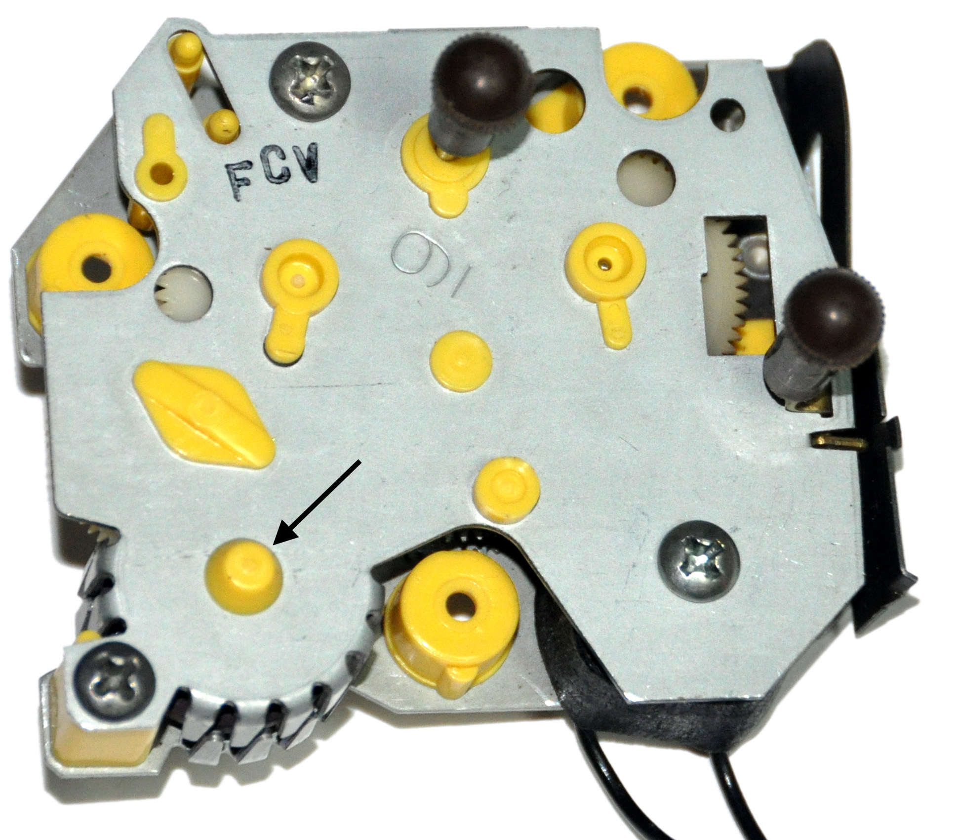
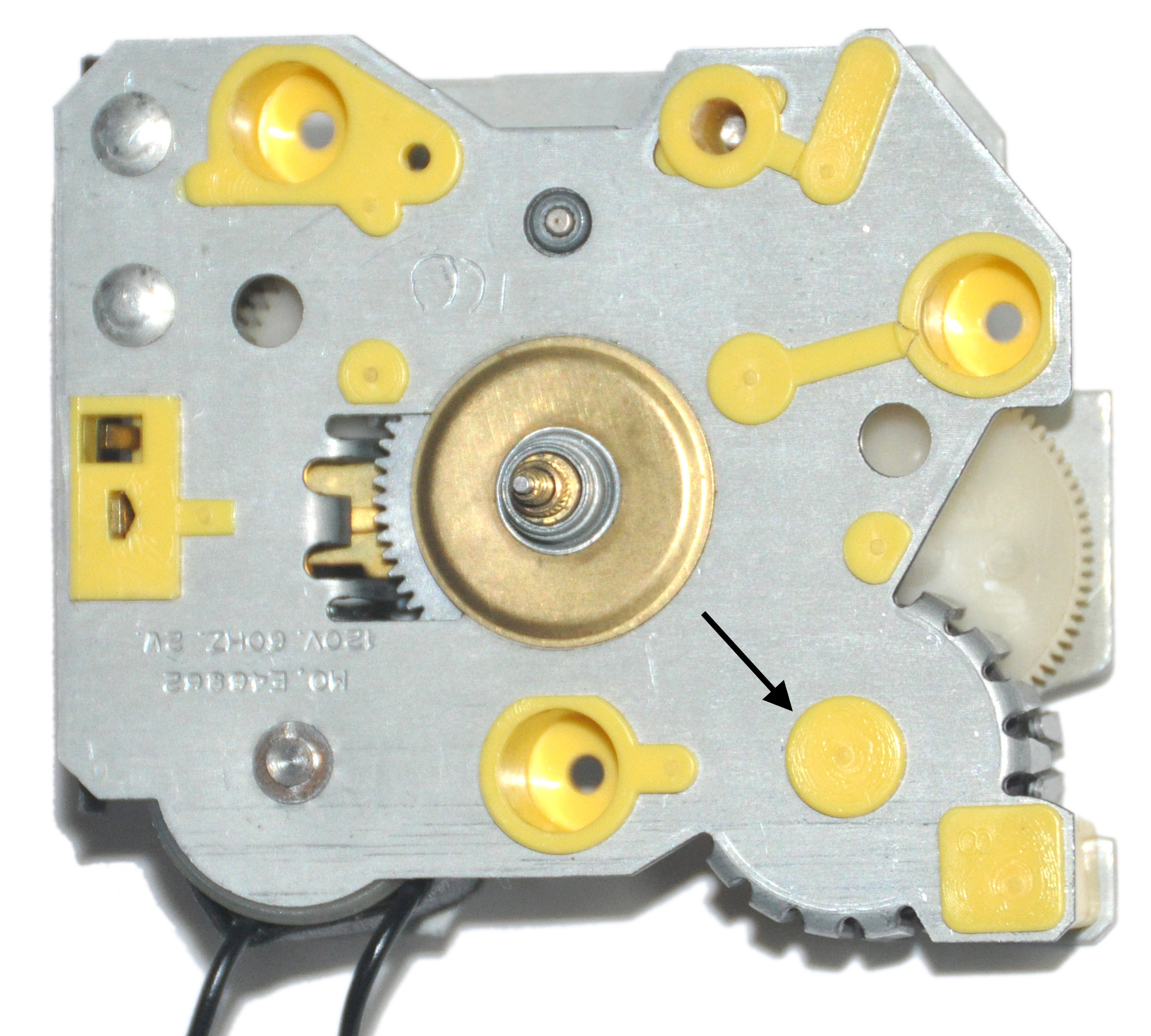
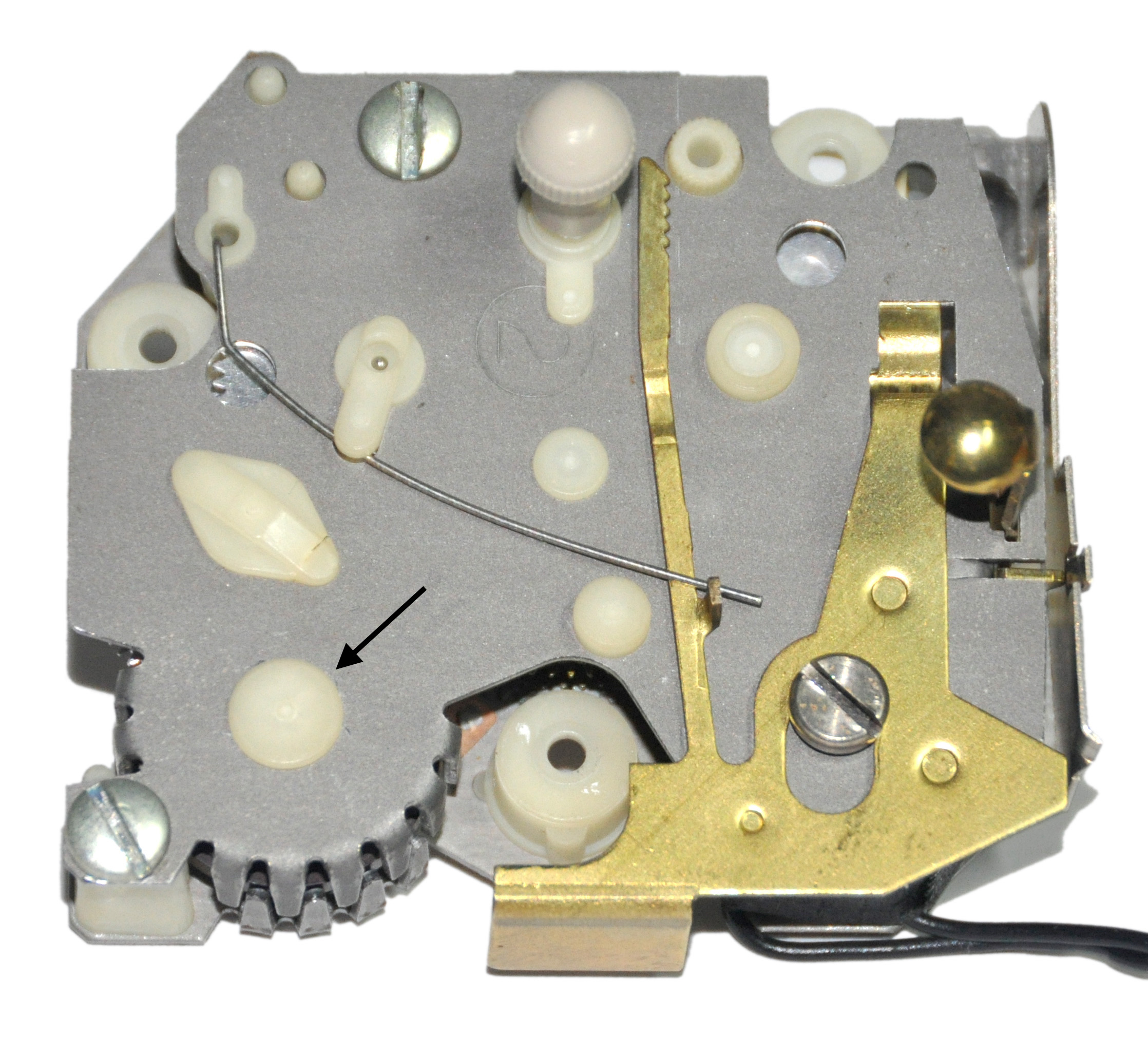
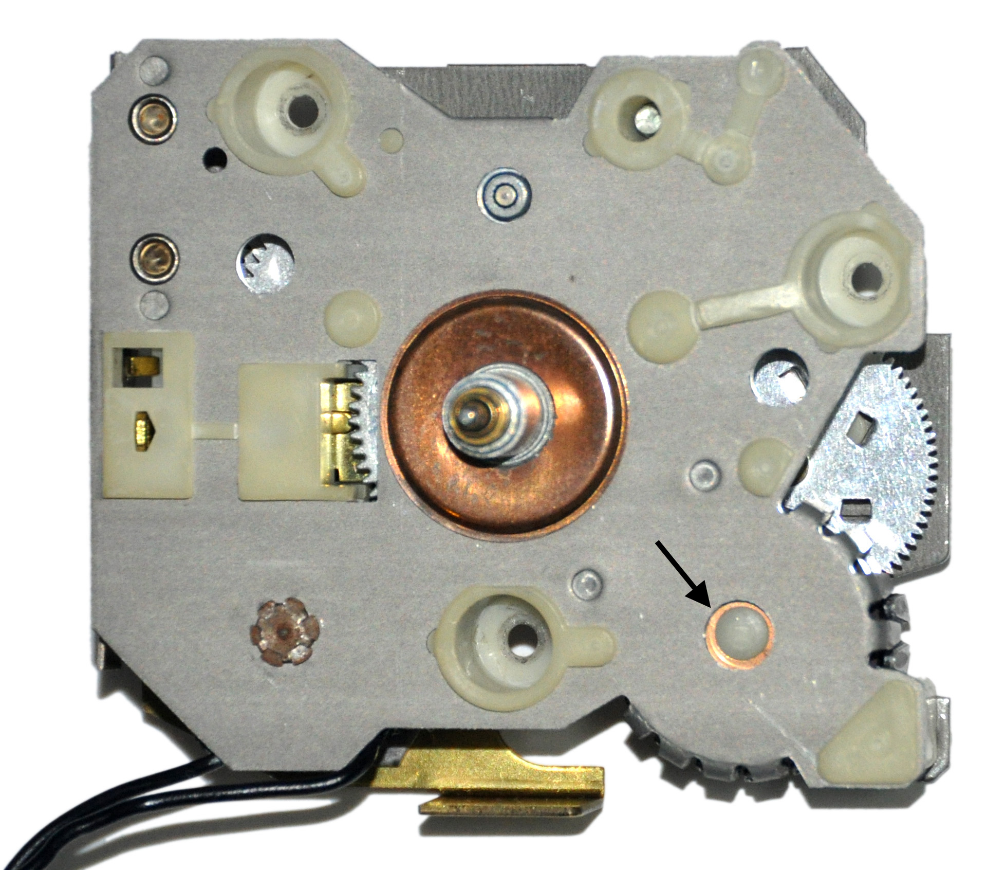
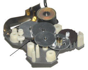
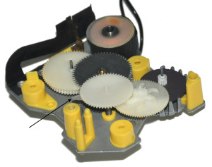
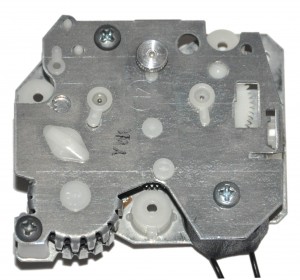
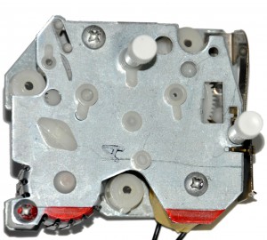
The first step to fixing one of these things is to be sure you indeed have one! The photos below show the front and back of two Sunbeam movements, one from about the mid 1960’s and one from sometime in the 1970’s. Both are from bedside alarm clocks. Similar movements were used in wall clocks, mantle clocks, etc, but all Sunbeam electric clock movements will look very similar to the photos below.
Between the older and newer movements there were several changes
-Some aluminium gears were replaced with nylon
-The plastic used for the bushings was improved and is less susceptible to breakdown.
-Motor rotor bushings redesigned (note the black arrows in the photos below).
-There are some minor changes to the shapes of the plates.
It is important to note which version of the motor bushings yours has since the older bushings often need replacement while the newer bushings do not. Section 7, ‘Replacing Motor Bushings’ only applies to the older bushings. See Figures 1.1 – 1.4 below to help with the identification. Note that the color of the plastic parts is not a good indicator. Instead, compare the motor bushings (marked with the black arrows) to correctly identify what version of the movement you have.
|
|
|
|
2. How I Designed The Replacement Motor Pinions
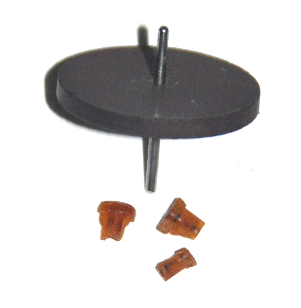
The primary cause of failure in these motors is the motor pinion. This small gear is press-fit onto the shaft of the motor rotor. The rotor itself is a piece of ferrite, a ceramic material which has a high magnetic permeability allowing it to ‘conduct’ magnetic fields. As the motor runs this ferrite becomes hot and this combined by the petroleum based grease originally used has badly degraded this pinion in nearly all of these movements. Often it is so bad that the pinion will crumble to bits when disturbed! Obviously this pinion needs to be replaced and due to the magic of 3D printing this is now possible! Although I was unable to find an intact original to work from, I have carefully re-engineered this pinion based on measurements taken from the wheel it meshes with and from a partially disintegrated original.

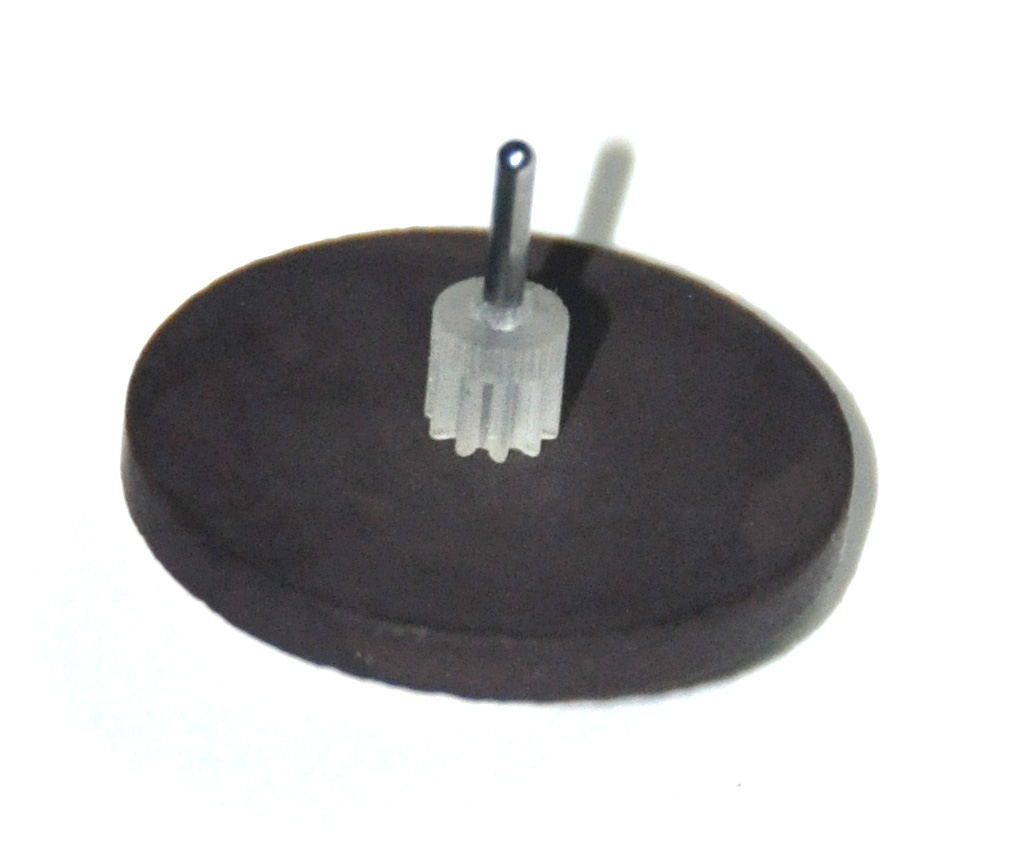
Figure 2.1: Remains of an original pinion next to the motor rotor
I first determined that the module of the motor pinion is 0.314 by counting the teeth and measuring the outer diameter of the intact wheel that it meshes with and then applying the appropriate the formulas at the link below.
http://www.metrication.com/engineering/gears.html
With the module known and knowing that the motor pinion originally had ten teeth by looking at the remains of an original I was able to use the tool below to generate a DXF file for the outline of the part.
http://hessmer.org/gears/InvoluteSpurGearBuilder.html
With the outline of the pinion known, it was a simple matter to estimate the depth of the hub and teeth from the damaged original and the inner diameter from the motor rotor shaft. A bit of work in Rhino 3D and I had an STL file for the part. Then with the magic of Shapeways Frosted Extreme Detail Plastic, I was able to have physical pinions created that fit and work perfectly! Better still, the acrylic the replacements are made of won’t degrade like nylon does so the replacements should outlive the rest of the clock mechanism. What follows is a guide to repairing these clock mechanisms, presented in the order which I recommend proceeding with such a project.
3. Disassembly
These movements are quite easy to work on. They can be disassembled by removing the three screws on the rear plate and gently pulling the plates apart. Remove the wheels one-by-one and note where they go to make reassembly easier. Do not attempt to remove the coil from the rear plate unless it is already damaged and you plan to rewind it as it is quite fragile and firmly pressed into place. Figure 4.2 shows a rear plate with all easily removable parts removed for cleaning.
4. Cleaning and Lubrication
I recommend starting a restoration of one of these movements by doing a complete cleaning and lubrication of the movement. even if it is clear from the start that some pieces will need to be replaced, doing a full clean-and-lube first will allow you to identify if any other parts need work so that you can order all the parts you need at one time.
For proper operation and long life it is very important that all of the old lubrication is removed from the parts and replaced with a quality synthetic plastic safe lubricant. After completely dismantling the movement, cleaning the parts is most easily accomplished with a small ultrasonic cleaner, but barring that careful use of a toothbrush, cotton swabs and toothpicks and isopropyl alcohol should suffice. If an ultrasonic cleaner is used, be sure to remember NOT to submerse the front plate as it has the coil on it. Do not attempt to remove the coil from the front plate unless needed as it is easily damaged. Also, so not put the motor rotor itself in the ultrasonic cleaner – the ferrite is can be damaged.
Special attention should be paid to the following trouble areas:
1) The insides of the hollow shafts on the alarm, hour and center wheels (gears) should be thoroughly cleaned of old lubrication with alcohol on a q-tip or toothpick. The alarm shaft can be easily cleaned out with a Q-tip, and the hour shaft can be cleaned out with a standard round toothpick, but the inside of the center wheel shaft is so small that it is tricky to clean. I have found that the easiest way to do this is to use a round toothpick which has been carefully whittled down with a blade until it will just fit in.
2) Special attention should also be paid to thoroughly cleaning out the clutch on the center wheel. This clutch allows the time to be set with the knob on the back and it frequently is found to be frozen from died lubrication. If this is the case and the set knob is forced, the minute wheel will be damaged (if that has already occurred see Section 5, ‘Replacing the Minute Wheel’.) Whatever method of cleaning is used (ultrasonic or manual) be sure that this clutch moves freely.
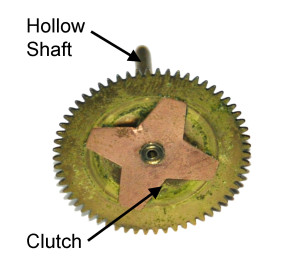
Figure 4.1: Center wheel before cleaning. Note the dried grease on the (frozen) clutch.
After thoroughly cleaning all the parts, the movement should be relubricated. To avoid long-term degradation, it is critical that a nylon-safe lubricant is used. Most petroleum-based lubricants are not, so don’t use anything that the datasheet does not explicitly say is plastics safe. Finding a grease which is the right thickness, is commonly available, won’t separate over time, is plastic safe, and works well enough under high load to properly lubricate the aluminium-on-steel center wheel clutch used in the newer movements proved challenging. However, after trying close to a dozen different lubricants I finally determined that NYOGEL 744 is a really good choice. It is a bit pricey, but is a really good grease for all manner of light plastic and metal mechanisms. You can order a tube from Micro Tools at the link below. If you use a different grease make sure that it is plastic compatible and make sure that when applied to the center wheel clutch it provides adequate lubrication to prevent binding.
http://www.micro-tools.com/product.htm?pid=133075&cat=14183
The following locations in the movement (and only the following locations) should be lubricated:
-All moving metal-on-metal parts (excluding gear teeth)
-The center wheel clutch (see the photo above. Make sure this part is well lubricated and operates smoothly to prevent damage!)
-The alarm cam mechanism (see photos below)
-The motor rotor ‘ratchet’ (see photo below)
-The motor bushings (Completely fill the bushings. The light damping action of the grease helps the motor run smoothly).
Use the lubricant sparingly. Do not lubricate the gear teeth or any plastic parts except for the motor rotor bushings and the motor ‘ratchet’ (which is made of plastic on newer movements).

Figure 4.2: Lubricate the alarm mechanism as shown
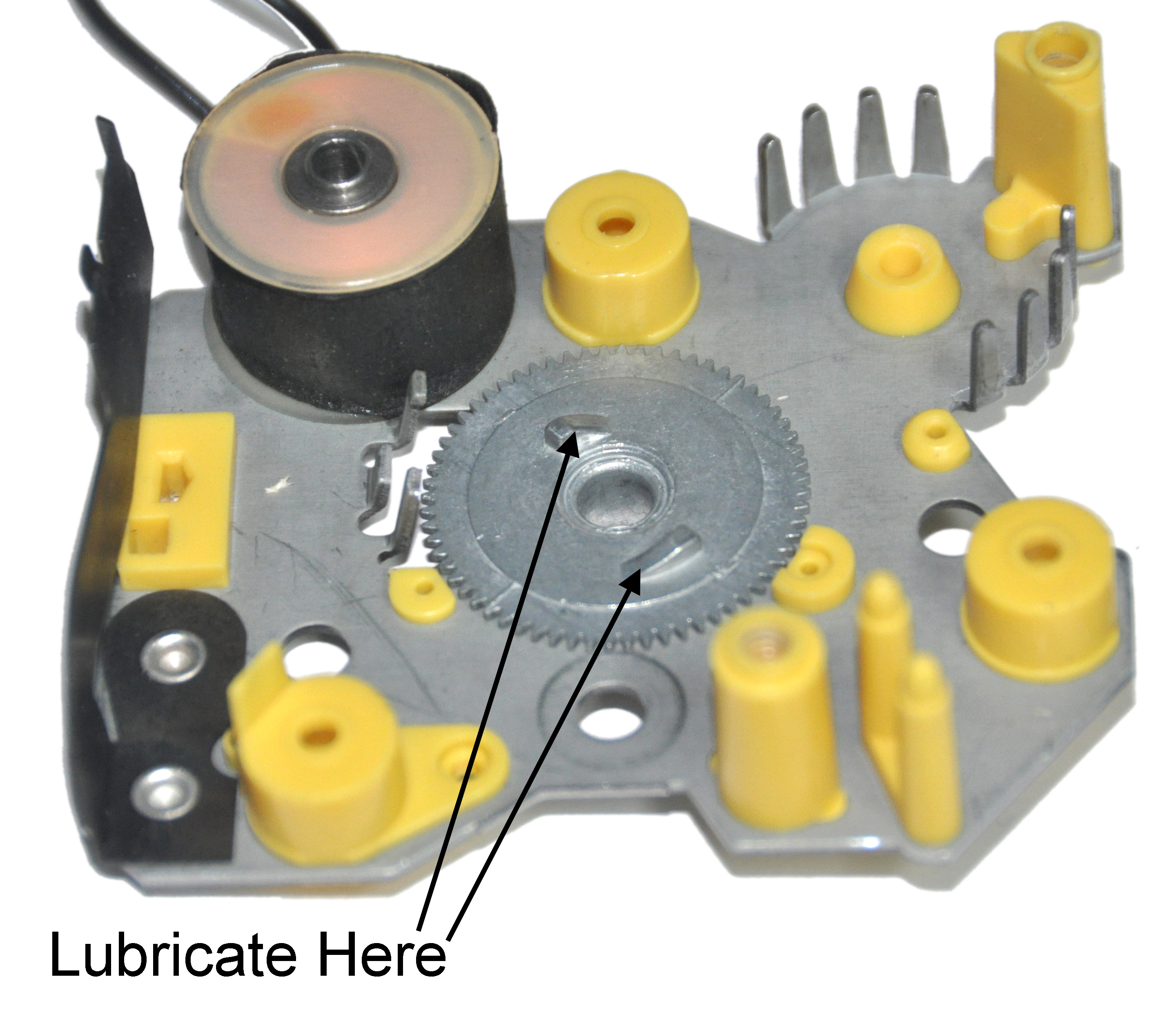
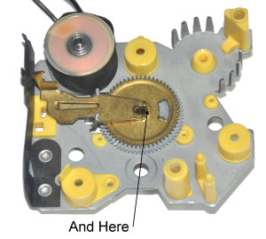
Figure 4.3: With the hour wheel installed, add a bit more lubrication to the alarm mechanism
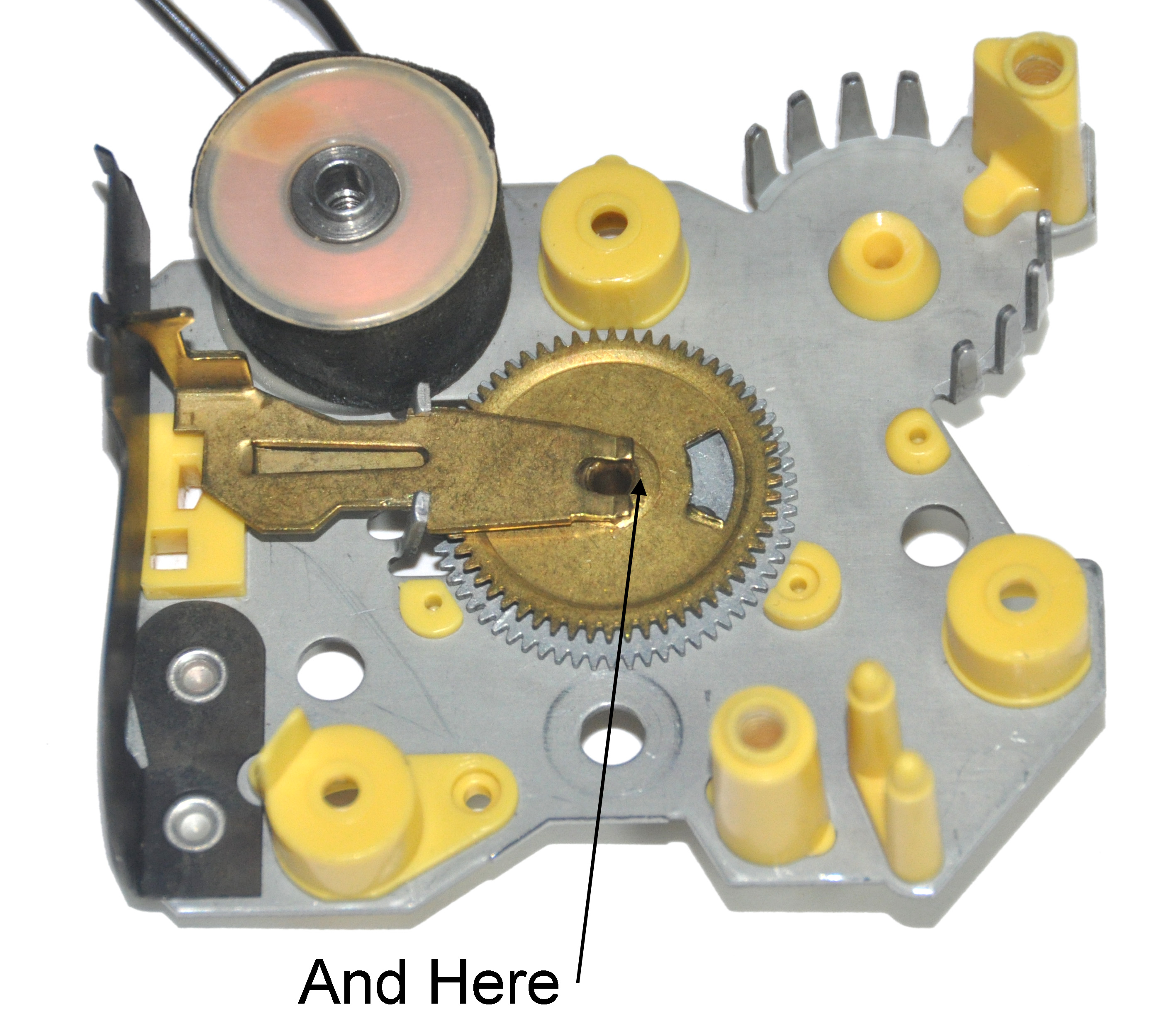
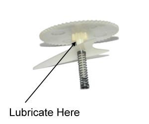
Figure 4.4: Lubricate the motor ‘ratchet’ where shown

With the cleaning and lubrication done, temporarily reassemble the movement (see Section 8 if you have trouble with this) and test it. Even if it works, read through the rest of the guide to see what parts are trouble spots that you might want to replace to assure reliability. Be sure to lubricate any parts you do replace as described above!
5. Replacing the Minute Wheel
The main function of the minute wheel, shown below, is to transfer power to the hour wheel from the center wheel and thus make the hour hand work. However it is also driven by the wheel on the time set knob when the clock is set. When the clutch on the center wheel gets gummed up with old lubricant, as often seems to happen in these clocks, and someone tries to force the set knob the additional torque applied to the minute wheel can easily strip some of its teeth, especially in the newer mechanism where the minute wheel is made of nylon. The significance of such damage can be hard to see, even under magnification and thus the best way I have found to see if the minute wheel needs replacement is to test it as described below.
After completing cleaning and lubrication and reassembling the movement, pull out the set knob and turn it clockwise to move the minute wheel through an entire rotation, then reverse direction and turn the minute wheel through another full rotation. If there is a problem with the minute wheel, a ‘clicking’ sound will be heard and the set knob will ‘pop’ over damaged gear teeth. This means the minute wheel needs to be replaced. Luckily, I have designed a replacement that you can order the at the D’Asaro Designs Shapeways Store. The replacements have been modelled after the nylon part used in the newer mechanisms as this fails much more easily then the aluminium one used in the older movements. However, it will work to replace either. It has also been strengthened, as compared to the original nylon part, in that the gear is 50% thicker and it uses a slightly different tooth profile with shorter stouter teeth.
Note: Unfortunately, despite my best efforts, the pinion on the new minute wheels appears to be more easily stripped then the original. I have seen them fail in clocks which run hot and require high torque on the hour hand. I recommend replacing this part only if absolutely necessary and take no responsibility if the replacement fails in short order.
Installing the new part is easy. After dismantling the movement and removing the damaged minute wheel, clamp one end of the steel shaft in a vice or a pair of smooth-jaw pliers between two pieces of brass or plastic to prevent marring. Then try to pull wheel off with your fingers by using a twisting motion. If you must use pliers, wrap the jaws in black tape to prevent damage to the wheel.
With the old part removed, carefully clean the shaft with isopropyl alcohol to remove all reside from the shaft. Install the replacement in the same orientation as the original. Clamp the shaft as described above and press the new wheel on with your fingers, again using a twisting motion. If needed, you can use a small block of wood with a hole drilled in it for the shaft to press it on, but don’t use pliers on the new gear – it is too brittle. Don’t worry if it is a bit of a tight fit – that is normal. The new part should be installed so that 2.0 mm of shaft is protruding from the pinion.
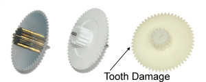
Figure 5.1: From left to right: Old style aluminium and brass minute wheel, replacement minute wheel installed on shaft with correct 2mm shaft protrusion, original non-functional nylon minute wheel showing (very subtle) tooth damage.
Reassemble the clock and repeat the test described above. The set knob should now work smoothly through a full rotation of the minute wheel in either direction.
6. Replacing the Motor Pinion
Because the originals are so failure prone, I strongly recommend that anyone working on one of these movements replace the motor pinion, even if it is holding up OK now, it is certain to fail soon. You can order a replacement pinion at the D’Asaro Designs Shapeways Store. It has also come to my attention that a replacement molded pinion is available on eBay. You can order those here instead of my 3D printed part if you prefer. The same part should work for all versions of this movement. When you receive the replacement, be sure to clean it thoroughly with isopropyl alcohol to remove any residual wax left by the printing process.
If the old pinion is completely disintegrated, just scrape its remains off of the shaft with a small blade. If it is reasonably intact you can try pulling it off the shaft. Clamp the other end of the shaft in a vice or a pair of smooth-jaw pliers between two pieces of brass or plastic to prevent marring. Then try pulling on the pinion with your fingers by using a twisting motion. If you must use pliers, wrap the jaws in black tape to prevent damage to the part. Never pry against the ferrite disc!
With the old pinion removed, carefully clean the shaft with isopropyl alcohol to remove all reside from the shaft, ferrite disc and new pinion. Install the replacement in the orientation shown in the photo below. Clamp the other end of the shaft as described above and install the new pinion with a your fingers, using a twisting motion. If needed, you can use a small block of wood with a hole drilled in it for the shaft to press the pinion on, but don’t use pliers on the new pinion – it is too brittle. Don’t worry if it is a bit of a tight fit – that is normal. When correctly installed the teeth on the top of the pinion should be just touching the ferrite disc.
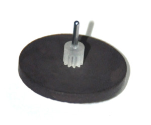
Figure 6.1: New gear installed on rotor shaft
DO NOT use the ferrite to support the shaft when installing or removing the pinion – it is very fragile and you don’t want to disturb its position on the shaft. However, if the ferrite is accidently moved, adjust its position so that it is exactly centered between the front and rear plates. Also, if it is worn and fits too loosely on the shaft, a single drop of super glue will secure it.
7. Replacing the Motor Bushings
First determine if you have the older or newer style bushings (see Figures 1.1-1.4 at the beginning of this article.) The old bushings were cone shaped with a spring to push them together, assuring that the rotor was always held in the exact center of the bushings with no side-to-side play. The new bushings are simple sleeves. As much as I think the old design is cleaver, the new one has proved to be much more reliable since the nylon used in the original was, like the motor pinion, prone to disintegrating due to heat and incompatible lubrication while the plastic and or lubricant used for the newer ones appears to be less prone to this. I have never had any trouble with the new ones and so I have not designed replacements. However, if you do find a movement with the new style bushings which need replacing, please contact me and I will see what I can do about providing some.
Assuming you do have the old style bushings, make sure you have thoroughly cleaned all the old lubrication from each of them. Use isopropyl alcohol and a toothpick to scrape off all remnants of disintegrated nylon and dried grease. With that done, examine the bushings carefully under magnification. The cavities where the rotor rests should be conical in shape and, most critically, each cavity come to a sharp and well-defined point at its center. It is this point which holds the rotor shaft in place and if it is badly worn or disintegrated the shaft will wobble from side-to-side, preventing the motor from starting reliably and running smoothly. The photo below shows a pair of original bushings.
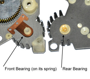
Figure 7.1: Original old-style bushings after cleaning. Note that the rear bushing is severely degraded and obviously must be replaced. The front bushing is probably serviceable but was replaced anyway as a precaution.
I have designed replacement bushings from measurements taken from originals. They, are, as with the the motor pinion, available in the D’Asaro Designs Shapeways Store and are made of the same durable acrylic plastic that won’t degrade like the original nylon. (Note that the rear motor bushing has been updated as of 3-3-2016 to better reproduce the original part.) When you receive the replacements, clean them thoroughly with isopropyl alcohol to remove any residual wax from the printing process.
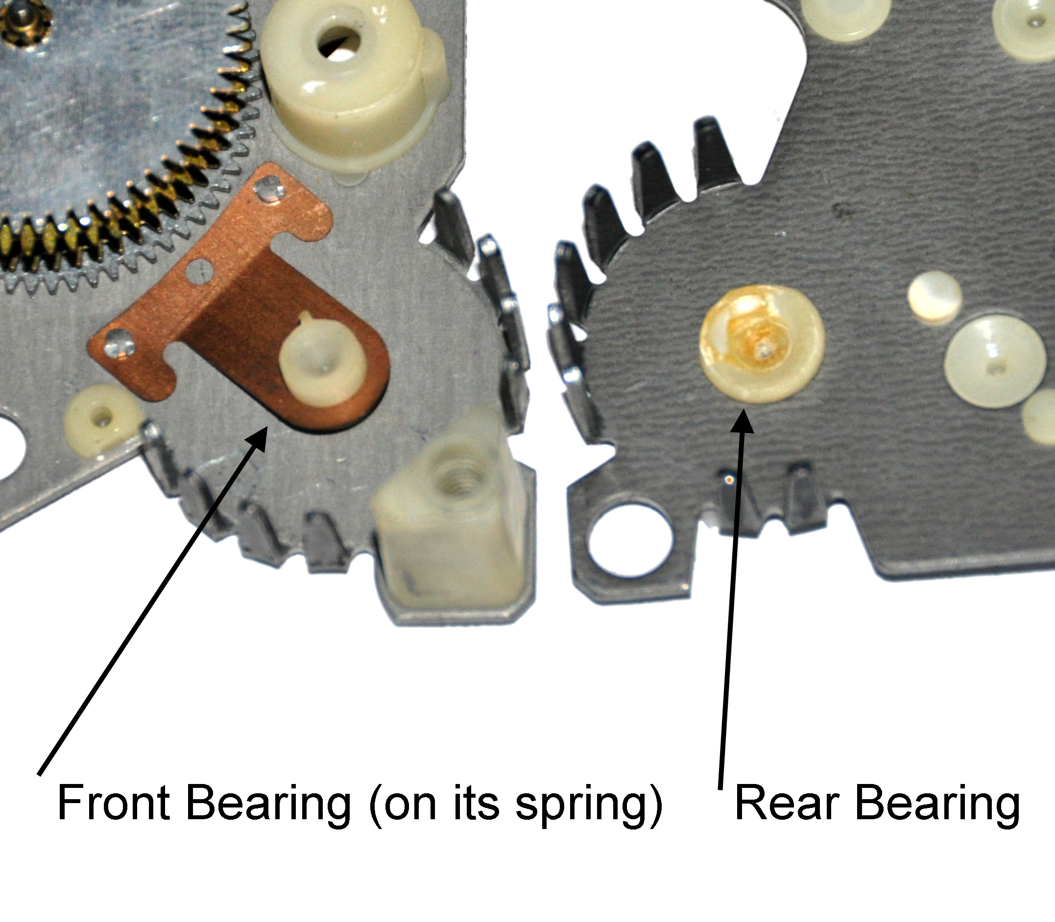
Replacing the front bushing is easy – simply lift out the original with a pair of tweezers and place the new one into its place. However, replacing the rear bushing is trickier since it is molded into the rear plate. The original could be drilled out, but I have found it to be much safer and less destructive to cut it free of the plate using a razor blade. Insert the blade as shown in the photo below and with a forceful a rocking motion carefully cut through the old bushing. It will then lift easily out of the rear plate.
Figure 7.2: Cutting the old bushing to remove it from rear plate
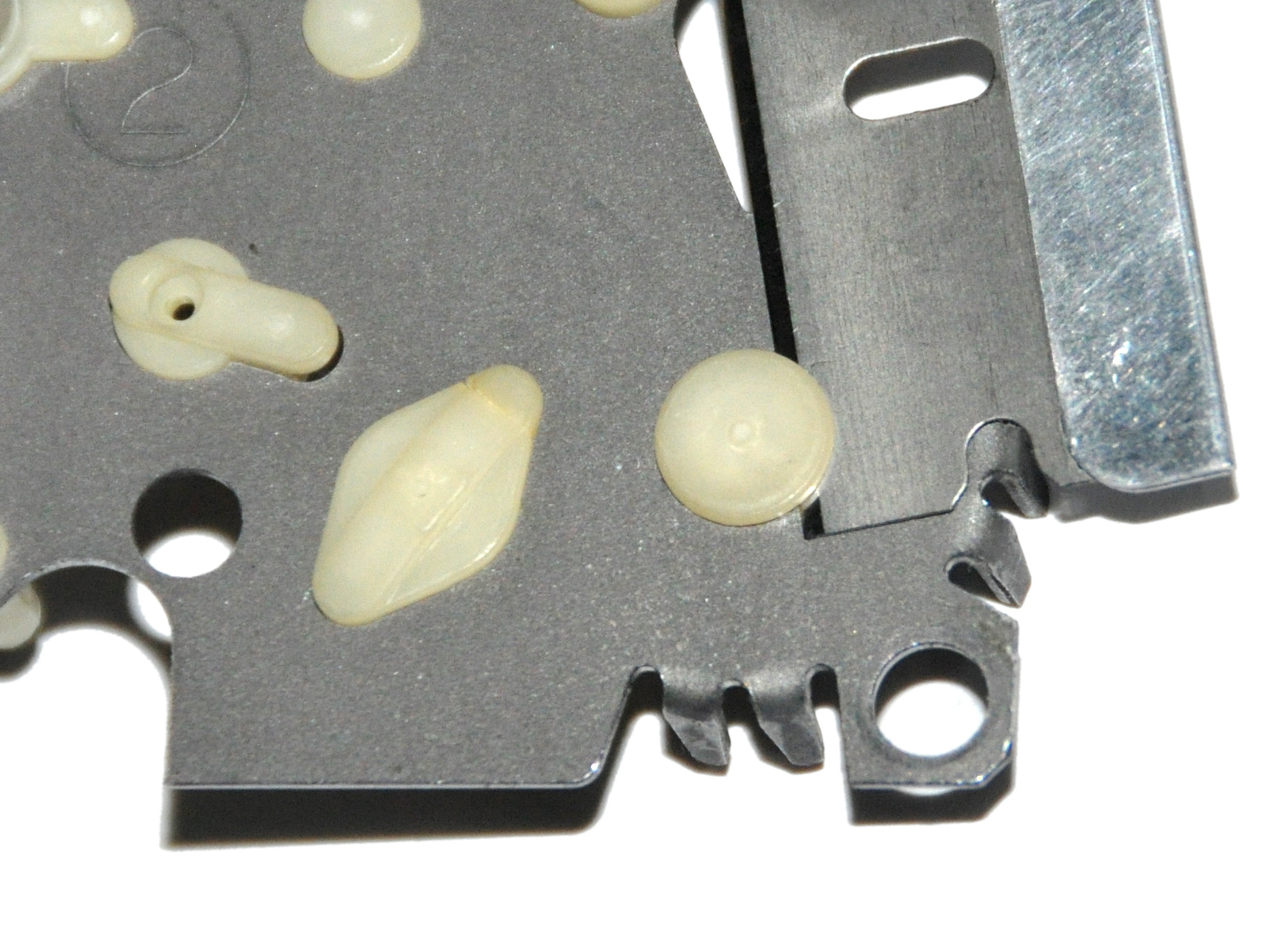
With the old bushing removed, the new one can easily be pressed in by hand. It should be pressed all the way in so that the body of the bushing is flush with the inside of the rear plate. It has been designed to be a press-fit so that it will stay in place during the assembly of the clock, but because of that it is important to be careful not to press on the portion of the new bushing protruding from the outside of the rear plate as doing so will unseat the bushing and misalign the rotor. An installed pair of new bushings is shown below.
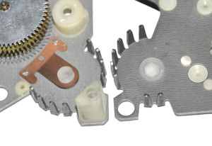
Figure 7.3: A pair of new bushings correctly installed.

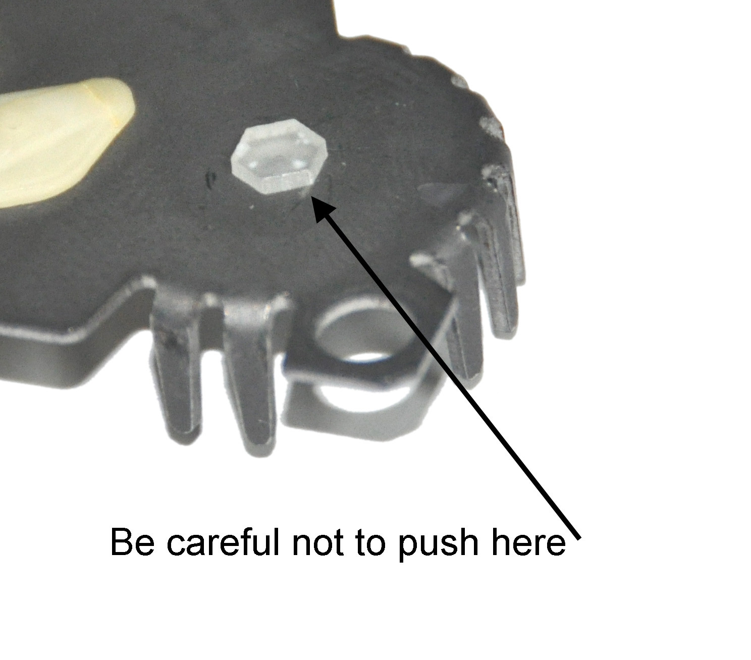
The photo below shows the back of the new rear bushing.
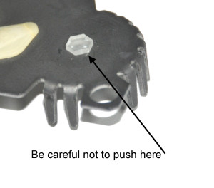
Figure 7.4: Applying pressure to this protrusion will unseat the new bushing. Be careful to avoid doing that
After the new bushings are installed, be sure to relubricate them as described in Section 4, ‘Cleaning and Lubrication’ before reassembling the clock.
8. Reassembly
In case you are having trouble getting all the parts back in the right locations, the photos below should help. Figure 4.3 is also useful, showing the correct installation of the hour wheel and alarm mechanism, as are Figure 1.1 – 1.4 which show the front and back plates of the correctly assembled movements.
|
|
When power is first applied to the motor, the rotor may appear to jitter for a few seconds or it may start going backwards. This is normal. The purpose of the ‘ratchet’ is to stop the rotor and cause it to reverse direction if it tries to start in the wrong direction. When running the motor should be nearly silent even with only very light gear noise with your ear right up next to it. If it is noisy or jitters excessively (more then 10 seconds or so) on startup, recheck the motor bushings for damage and be sure that they are clean and completely filled with grease.
To reinstall the hands of the clock, follow this procedure to make sure that they are all in proper adjustment.
1) Install the alarm hand if present. Do not worry about its adjustment at this time.
2) Install the hour, minute, and second hands so that they are all pointing exactly at 12:00.
3) If the clock has an alarm, turn it on by pulling out the control.
4) Pull out the set knob and turn it counter-clockwise until the alarm just starts going off.
5) Adjust the alarm hand until it points to the time shown by the hour and minute hand.
6) Pull out the set knob and turn it counter-clockwise until the alarm stops going off
7) Turn the set knob to set the alarm for 12:00
8) Repeat starting at step 4 until, with the alarm set to 12:00, it goes off at 12:00 exactly.
9. Conclusions
These little clocks might not be worth must, or be the best ever made, but they are a lot of fun and work really well when properly rebuilt. I hope this article helps save a few more from the trash! Here are photos of the two clocks, assembled and working, that I rebuilt for this article.
|
|
Download the 3D models in Rhino 3D and STL format for this product here. Note that these files are available for PERSONAL, NON-COMMERCIAL USE ONLY. In short, you are welcome to use them to build this product yourself, but you must contact me to work out a commission if you wish to sell anything derived from them. This product was designed in Rhino 3D so you will need to download get copy of that software from rhino3d.com before you can use the files.
10. Addendum (Added 3-5-2016)
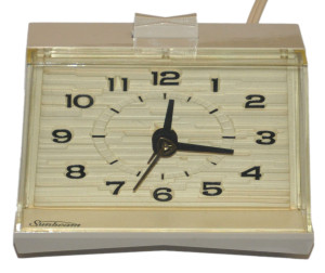
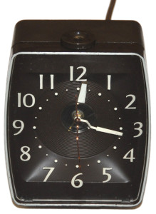
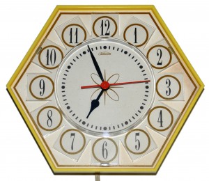
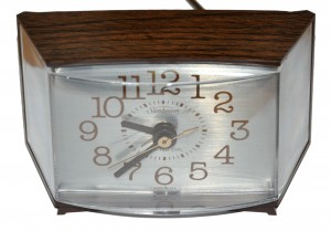
I had so much fun fixing up the two clocks described in this article, that I decided to do another pair. A quick search of eBay turned up two “parts or repair” Sunbeam clocks in nice condition. One is a lighted dial alarm clock with the new style movement and the other is a kitchen wall clock from 1967 with the old style movement.
Both came with their original boxes and appeared to hardly by used. None the less, the motor pinion in each one had completely disintegrated. Luckily nothing else was wrong and I was even able to get better measurements for my replacement motor bushings off of the 1967 kitchen wall clock. Figures 10.1 and 10.2 show the movements for these clocks and Figures 10.3 and 10.4 show the clocks themselves.
|
|
|
|
With these two fixed, I am starting to build up a bit of a collection. Figure 10.5 shows them displayed by my TV.
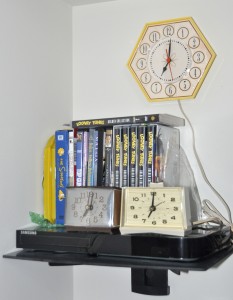
Figure 10.5: Part of my collection of Sunbeam clocks. All were repaired using the parts and techniques described in this article.
Each of these clocks came with its original box. Figure 10.6 shows them arranged in the same positions as the clocks that came out of them. Interestingly, none of these three clocks appears to have been used, at least not much, but they all had their motor pinions fail. It appears that time alone, even without heat, is enough to do it. Thanks to 3D printing, this luckily isn’t much of a problem!
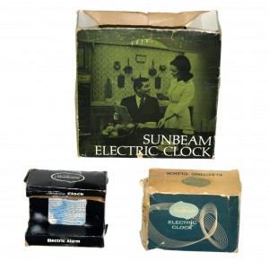
Figure 10.6: The original boxes for the clocks in Figure 10.5.
Happy collecting!
-Matthew
This was very interesting. I find these great movements to work with, especially because they fit modern clock hands. I have a ton of these things that I am working on that all need the replacement pinions. I have done a few with pinions from another place, but I have never seen the bushings available before. I would say that most of my NOS movements are the older design ones, but I do have a few newer ones. I will definitely save your store for the near future, once I decide to dive into the rest of my movements.
Thank you so much for the positive feedback. I am glad you found my article useful. I am curious though, who else sell the pinions? I would be happy to add a link in my article.
-Matthew
A person on eBay does. I can give you a link to the eBay store if you want . They don’t always have them, but usually they do. The only difference is their pinion gears are made of Delrin. I have been using them for about a year with no problems at all.
Link to their eBay store: http://www.ebay.com/usr/hippogardening?_trksid=p2057872.m2749.l2754
Hey, I bought a few of the motor pinions and they work great. I have a suggestion for a part you should make, the little gear the controls the snooze feature on some clocks. I have had a few fail on me in the past so I figured you could try and have them made and see if they hold up.
Hi. Thanks for the message. I am so glad that my parts work for you! As for your request, can you be a little bit more specific? Is this the gear that is used on Sunbeam movements or some other brand? If another brand, please specify an exact model so I might be able to look into getting one to use as a model.
-Matthew
Sorry for the late reply, yes the gears on the Sunbeam motors.
Wow, you’re certainly an authority on the subject! If you can help me skip directly to “go” how do I either replace the mechanism (on the back) or the entire clock? Ours is the Sunbeam Quartz 093-150347 w/ the 7 3/4″ diameter face (measuring from inside, bezel to bezel, 12 and 6 o’clock. Part of our very recent kitchen remodeling job was having the accent ring of this clock painted to match some of the other highlights in the kitchen. I know, cost more than the clock to have done! But now even new batteries aren’t the solution for it keeping time. Suggested replacement part? I sent a note via the “contact us” link to clockparts.com over a week ago and still haven’t heard back from them and hey, I’m losing time over this! 🙂 Appreciate any direction, peter peterbbell@gmail.com
Sorry, I don’t know anything about replacing movements, nor do I really approve of the practice as it “ruins” a vintage clock.
-Matthew D’Asaro
I recently worked on an old style movement with an intact set of motor bushings and realized that my original design for the rear motor bushing differed slightly from the original. I have since updated (and tested) the design both in the files available at the end of the article and on Shapeways. I don’t think anyone bought one of the old parts, but if you downloaded the files to make it yourself before 3-3-2016, I would recommend downloading them again to get the update.
-Matthew
How do I get the two wind up knobs for a little mermaid clock
Thank you for the comment. I am sorry, but I have no source for those parts.
-Matthew
The repair f my Sunbeam clock went well. Thank you for your information.
Now, I have a clock with the first gear after the motor worn. There is no name on the motor or the movement, the clock is a Swing Clock Mfg. Co. The gear is a fiber gear about
2 1/4″ in dia.
Can you steer me in the right direction?
Thank you, Mike
Thank you for the message! I am glad your repair went well. I don’t currently offer a replacement for that part, but if you send me an email (use the contact link at the top of this page) we might be able to work something out.
Matthew
I have an electric sunbeam wall clock that has the movement shown in figure 10-1. It works great except it is super noisy but ONLY when it is on the wall in the proper position. If you lay it flat or hang it upside down, it is nice and quiet. Any thoughts? Thanks.
Sylvia – Thanks for the comment. It sounds like your clock is in need of cleaning and librication and maybe a new motor pinion or motor bushings. Sorry I can’t be of more assistance. I don’t have shop space anymore and can’t take on any projects right now.
Matthew
Hello, enjoyed and appreciate your Article on repairing Sunbeam alarm clocks. I would like to order the motor bushings and motor pinion. And what ever else you might recommend. Can I call or do I do this on your site. Thanks from a guy who appreciates old technology and can’t stand to see it tossed in the trash. Mike in Melbourne, FL.
You can order the parts directly from my Shapeways store D’Asaro Designs Shapeways Store. However, OTHERS HAVE RECENTLY HAD PROBLEMS WITH PART QUALITY FROM SHAPEWAYS. ORDER AT YOUR OWN RISK.
Hello I have a master crafters Clock happy time. It is in a very bad condition. Any clues of where can I send it for repair in Germany?
Sorry. I am pretty much out of business for the foreseeable future. I no longer have my lab setup after I moved to Seattle to take a new job and don’t have the time to work on this stuff either. Good luck with your project.
-Matthew D’Asaro
Matthew, if possible could see how the time set cog is set. I took apart a sessions electric mantle clock and I can not figure out how to get the time setting cog to work. A picture or a link to one where I can see what I need would be helpful. I have been scouring the net for days.
I am sorry, but I don’t have any additional photos beyond what is in the article.
-Matthew
I was able to bring a mastercraft waterfall model 344 back operating with use of your site. I paid $3 for the clock and something like $12 for the gear off ebay. A couple hours invested in cleaning it up and put it back together 5 times and it is good to go. Thanks
Thanks so much! I am really happy the parts worked for you.
-Matthew D’Asaro
do you still offer parts for sale? Looking for the pinion gear. Thanks
They are available at https://www.shapeways.com/shops/dasarodesigns