Fixing an HP / Agilent 54845A infinium Oscilloscope
Last spring (2014) I came across what seemed to be an amazing deal at the MIT Swapfest. It was a HP 54845A digital oscilloscope, which, although over 15 years old, was still a pretty impressive beast being four channels, 1.5GHz, 8Gs/s! The only problem was it didn’t work. In fast the seller was letting it go cheap at the end of the meet because someone had bought it earlier in the day and then insisted on returning it again after they saw that all four channels appeared to be bad. Seeing that it was worth over $500 on eBay broken, I handed over my $240 and took it home figuring I had nothing to loose.
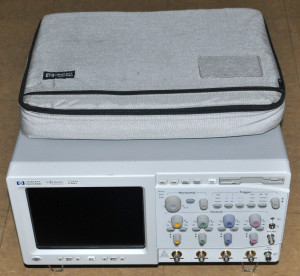
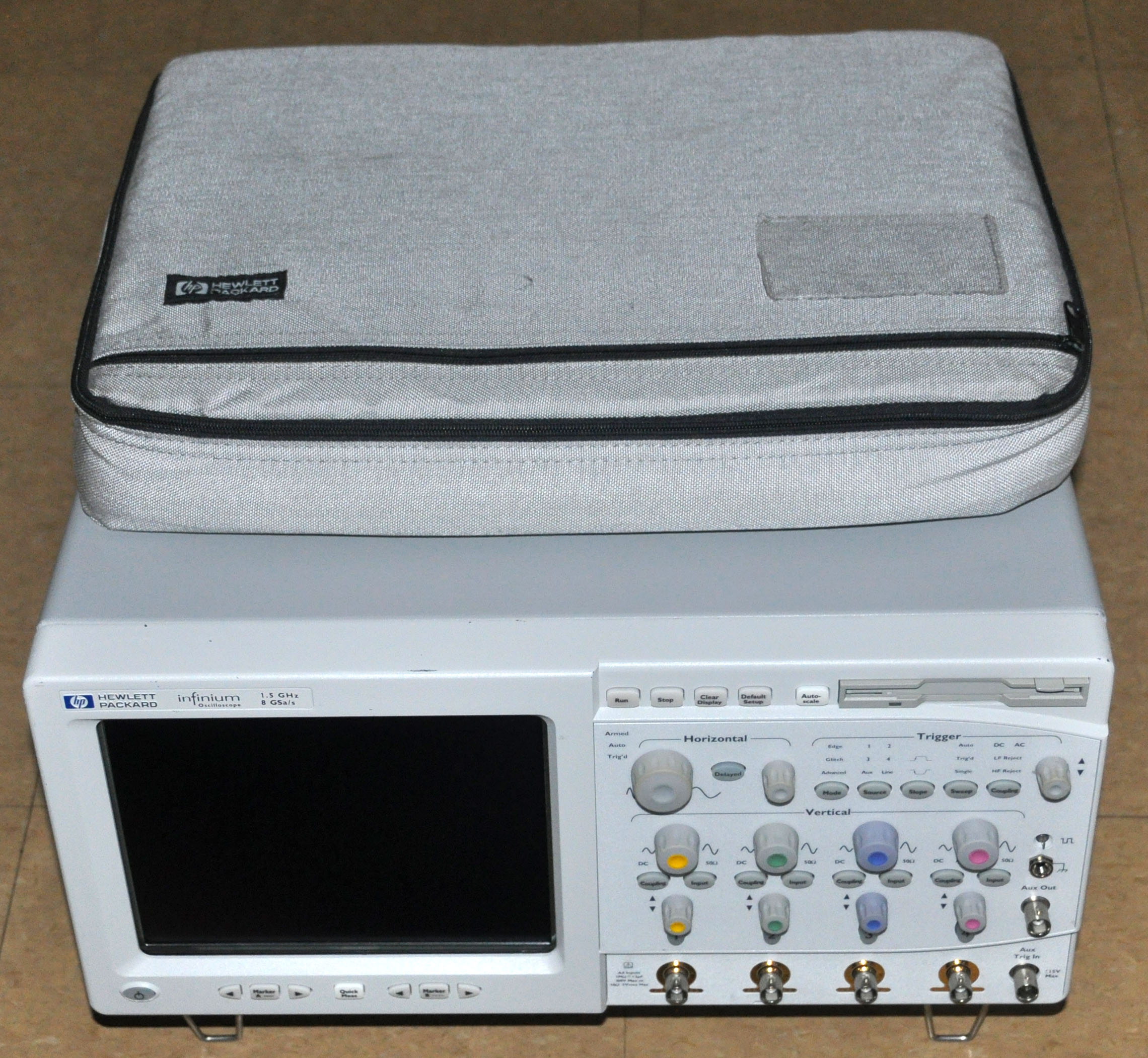
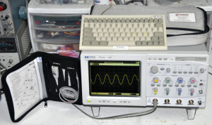
My HP 54845A Infinium (or is that Infiniium???) after I had cleaned it up some.
When I got home play with it a bit, it quickly became clear that the previous buyer was correct. Although the oscilloscope booted fine (it runs Windows 98), all four channels were railed high and the traces could not be brought onto the screen using the offset controls or by applying a reasonable negative voltage to the input. The behaviour was the same in 1M and 50-Ohm modes. Running the self-test showed numerous errors. Specifically:
-A to D converter
-FISO
-Offset Dac
-Gain
-Trigger level
-Pattern trigger
-State trigger
At this point, I took the unit apart and started checking for anything obvious. The voltage outputs from the power supply were marked and all checked fine for voltage and ripple and the computer motherboard and special video card seemed to be working fine since the thing booted, so that meant that the problem was on the acquisition board.
I downloaded a copy of the service manual from Agilent (now KeySight) but it is only an assembly level manual and doesn’t provide much more then a brief theory of operation on the acquisition system, so I figured I would have to figure it out myself.
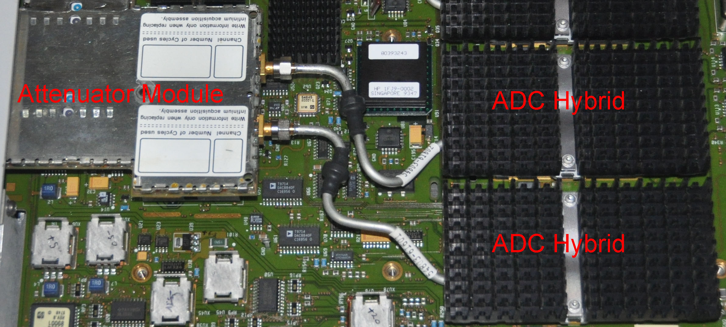
Looking at the manual and the acquisition board it was pretty clear that each channel of the acquisition system has two main components – an attenuator / pre-amplifier assembly to precondition the signal by amplifying / attenuating it to a known level and an analog-to-digital (ADC) hybird to convert the conditioned signal to digital. See the photo below.
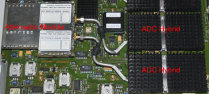
Photo of the acquisition system components. Note that each attenuator / preamp assembly handles two of the four channels. This is so that two of the ADCs can be interleaved to achieve the highest 8Gs/s sampling rate.
Understanding this, it was pretty obvious what the next test should be: to see if the problem was due to the attenuator / preamp assemblies or the acquisition hybrids, I disconnected the semi-rigied coax connecting them and injected a small signal directly into each of the acquisition hybrids. Under this condition, I got a nice clean trace on each channel, proving that the acquisition hybrids are still good. Furthermore, when I re-ran the self-test with the attenuator assembles disconnected, the A to D converter and FISO tests passed! Measuring the voltage on the output from the attenuator / preamp assembles, I see about 1.7V DC, which is consistent with the symptoms. With some more careful examination I was able to identify the trigger signal out pin on the attenuator module and when I injected into this, the trace could be triggered!
This was very good news – the ADC hybrids, triggering system, and digital systems all worked. ‘All’ I had to do was figure out why the outputs from the attenuator modules were stuck high. There were two basic possibilities. Either there was something on the acquisition board, in common with all four channels which was wrong (such as a supply rail) or else both attenuator modules were blown. It was not obvious which of these was true. On one side, it seemed quite improbable that all four channels would be blown out in exactly the same way, but, there was quite a bit of evidence on the other side as well. First, two channels go into each attenuator module, so it seemed that if one channel was blown it might take out the other one as well. All four attenuators looked like they were blown – putting out an unchanging DC voltage with no input. Furthermore, it was clear that I was not the first one to have worked on this. One of the attenuator modules was marked with an ‘X’ and while it was labeled as being for the channel 3 & 4 it was installed in the channel 1 & 2. It was even missing a small surface mount transistor and showed other signs of rework (more on this later). This seemed to indicate to me that someone might have tried to fix a blown attenuator and failed and then when the second one blew out the scope was scrapped. Finally, being that I work with students a lot I am used to seeing equipment blown in stupid ways. Students do odd things like connect a circuit to a scope channel and if nothing shows up, try the next channel, and the next…
Determined the figure out if there was something wrong in common with all the channels, I went to work reverse-engineering the pinout of the connectors which attach the attenuators to the acquisition board looking to see if I could identify a missing negative supply rail. I did this by measuring the voltages and waveforms at each pin with the attenuator module installed or removed. I made some progress but couldn’t identify any obvious missing power supplies. My progress was hindered by two things. First, HP used many odd-value voltage supplies (3.1, 6.3, etc.) which were hard to know if they were correct or not. Second, I couldn’t see the circuitry on the attenuator modules because of the soldered-on metal shields which also prevented me from probing the pins with the attenuator installed unless I held the entire acquisition board up on end hanging out of the side of the oscilloscope. Finally, some voltages seemed to change depending if the attenuator was installed or not and I couldn’t figure out if this was right or not. In short, the attenuator modules seemed to be getting +5V and -5V, so I was getting more and more convinced that they were probably blown.
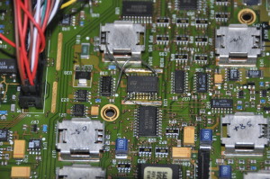
I also tried measuring the outputs from the numerous small regulators scattered over the acquisition board, but all the ones from fixed regulators for which I could easily determine the correct output voltage seemed reasonable. The photo below shows the voltages I measured on these (all readings here were verified to be correct after the scope was fixed):
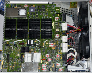
Output voltages of regulators on the acquisition board (not comprehensive).
At this point, having found no smoking gun, I pretty much gave up for the time being. I tried asking on the HP / Agilent Yahoo group here hoping someone else had already measured the voltages on the attenuator module connectors so I could compare mine, but no one had. I figured that I might be able to find another broken scope to compare with on eBay, so the project sat for a year while I waited for one to come along at a reasonable price.
When, after a year, I hadn’t seen one sell for less then $700, I decided to give mine another look. This time, I would take the rather drastic step of removing the soldered-on metal shields from one of the attenuators in the hopes that that would reveal enough about its circuitry to see if I could understand its pinout and determine, once and for all, if a supply rail was missing.
Removing the shields was tricky but not as bad as I thought. By using my Hakko 472 vacuum de-soldering station to remove most of the solder and then gently prying to crack free what was left, I was able to remove the shields from the attenuator which showed previous signs of rework without significant damage to the attenuator or shields. With them off the attenuator board was exposed. See the photos below.
Attenuator module without shields. Note the heavy rework on the top of the attenuator (top photo) and the missing transistors (Q2) (bottom photo). The two SMD capacitors taped on with Kapton fell out when I removed the shield. There are none missing, so whoever did the rework apparently accidentally left these inside!
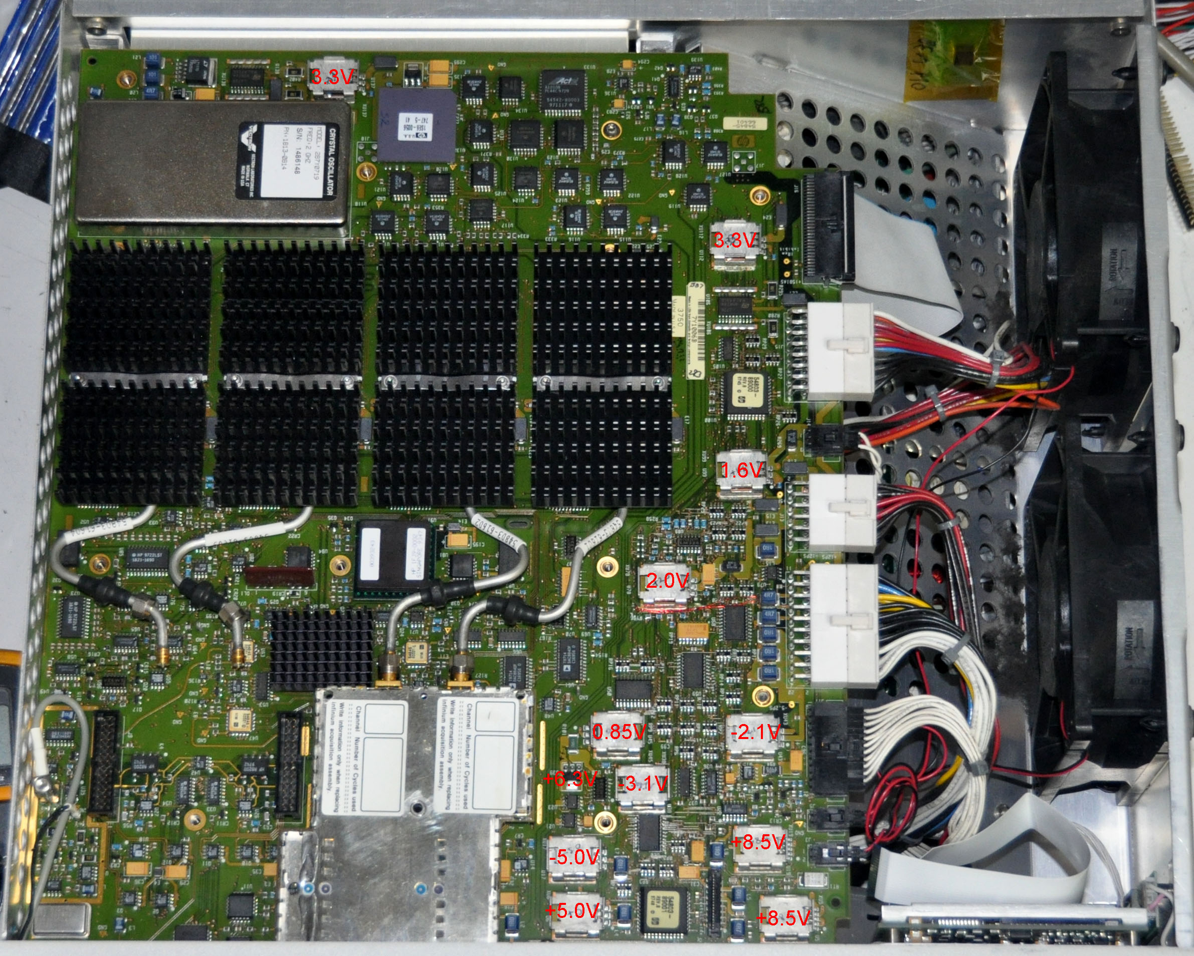
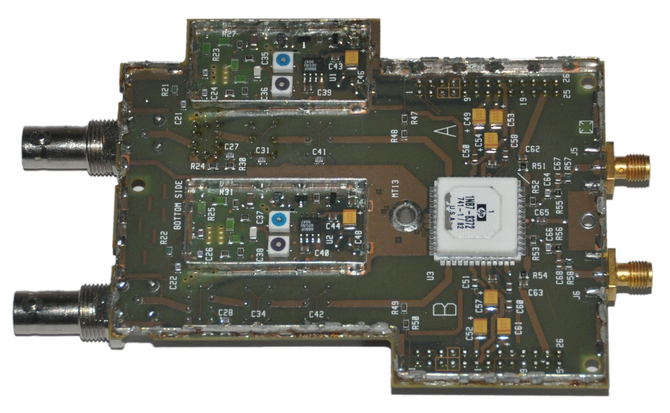
With the shields off, I was surprised at how simple the device is. There are only three ICs in the attenuators – an HP custom preamp hybird, P/N 1NB7-8372, and two Burr-Brown BUF601 50-ohm buffers for the 1M path (the datasheet for the BUF601 can be found here). There are also four relays per channel. K2/K6 (datasheet) are for switching the signal path between the 1M and 50-ohm paths, K2/K7 (datasheet) are x10 50-ohm attenuators, K4/K8 (datasheet) are x5 50-ohm attenuators, and K1/K5 (datasheet) are relays for x10 1M attenuators. I even tracked down the datasheets for all of the individual smd transistors and diodes, both to help me understand the circuit and to be able to replace the missing Q2. Most were pretty easy with the help of smdcode.com, but the one I really needed, Q2, was tricky. The part is marked ‘117’ but it turns out that the ‘7’ is a lot/date number of some kind and the part designation is ’11’. Once I figured that out, it was clear that the part is an MRF9511LT1 and was able to order one on eBay. See the photo below for the part numbers of the other discrete semiconductors.
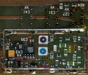
This closeup shows both the heavy rework (not by me) present on the attenuator as well as the part numbers of the discrete semiconductors. The device on the far left is a BAV99 ultrafast diode marked ‘A7T’. Next is a BRF92 NPN microwave amplifier transistor marked ‘P1p’. On the right is the impedance converter FET used to connect the 1M path to the 50-ohm path. It is of type 2SK501-52 and is marked ‘K52’.

With the basic structure and function of the attenuator module figured out, I went to work trying to see about the power supplies. I noticed right off that there six tantalum capacitors connected near the hybird – clearly power supply bypass capacitors! A bit of tracing and measuring the voltages on the header in the scope revealed that two are for the +5V / -5V supplies for the BUF601 chips and one is a digital +5V supply for the internal offset DAC in the hybrid. That left three capacitors for the hybrid analog rails. With the attenuator installed in the scope, these measured +6.3V, +3.9V, and +0.8V! There was no working negative supply! I could tell that the +0.8V one was the problem as its capacitor was connected with the correct polarity for a negative voltage. Removing both attenuator modules and remeasuring showed this supply at a much more reasonable -3.1V. If either attenuator was installed, though, the supply went back to 0.8V. This left two possibilities. Either the attenuators were something wrong with the supply so that it couldn’t source sufficient current, or both attenuators were blown and shorted, loading down the supply
To figure out which it was, I connected the attenuator to the oscilloscope on extension cables. I used 52 of the little jumper wires that I sell with my EPROM Programmer Universal Adapter plugged into pieces of header and two SMA extension cables to do this. This allowed me to connect an external lab supply to the supply rail in question on the attenuator without risking damage by applying power backwards to the regulator on the acquisition board. At this point I didn’t know what voltage that rail was supposed to be, so I figured that I would turn on the oscilloscope and then very slowly turn up the lab supply while watching the current carefully to see if I could bring the trace back onto the screen. This procedure worked, but seemed to reveal that the hybrids were in fact blown – the trace could be brought onto the screen, but its offset was extremely unstable and it would only pass a very distorted signal per the photo below.

Photo showing the extension cables connecting the hybrid to the oscilloscope and the very distorted trace.
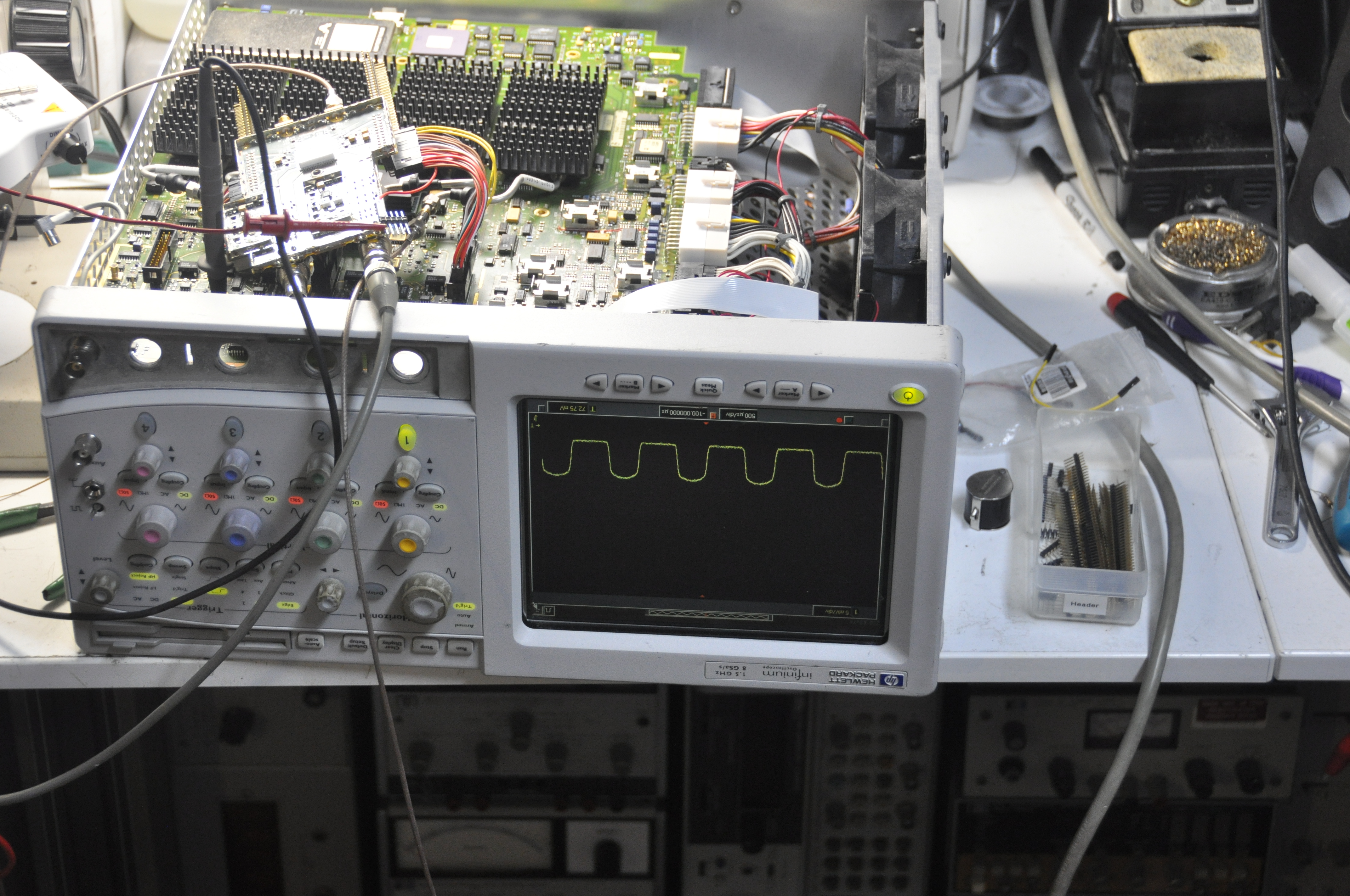
I was about to give up – both hybrids were presumably blown, when I figured I would try one other experiment. I set the supply to the full -3.1V which I had observed on the rail with the attenuators disconnected before starting up the oscilloscope. Amazingly, when I did this, it resulted in a clean, clear, stable, triggered trace! It worked! Better still when I tried the other attenuator module, it worked too! A bit more experimentation revealed what had happened. It turns out that this beast has automatic offset correction of some kind. It appears that when the oscilloscope is first turned on the offset in each channel is measured and used to program the offset DACs in the hybrids to correct for it. Thus, when I was turning on the oscilloscope with no -3.1V supply, this algorithm was railing the offset correction. My externally supplied voltage, set to produce zero offset, was then wrong in the other direction to correct for the railed DAC, resulting in a very weirdly biased amplifier and the distorted signal. The photo below shows the oscilloscope when it first worked for me!
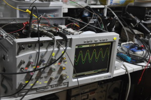
Photo showing the oscilloscope working with a nice clean trace. Hurray the hybrids are good!

Now knowing that the problem was with the -3.1V supply, I set about trying to figure out what, exactly, was wrong with it – the behaviour was really quite odd. When the oscilloscope was turned on with no connections to the -3.1V rail, the rail shows -3.1V. However, if any significant load (more then a few 10’s of mA) was drawn from the -3.1V rail, it would suddenly switch to being positive and would stay that way until the oscilloscope was power cycled – even if the load was removed. Some quick work with an ohm meter showed that the supply was fed from U38, an L2726 dual-output high output current opamp under a soldered-on heatsink. I removed the heatsink with a hot-air gun and started trying to trace out the circuit for the supply. U38 was just wired as a buffer, and when the supply would go positive after having been loaded, the non-inverting input to U38 would be at -10.5V, below its -5V negative rail. Thus, I wasn’t sure if the problem was with it, or with the circuitry driving it. I was suspicious that the supply, which has some kind of current monitoring, was shutting itself off due to a perceived overcurrent fault. Thus, I traced out the circuit and created the partial-schematic shown below. Note that this shows only the main regulation loop for the supply, not the current monitoring (or anything else that might be going on).
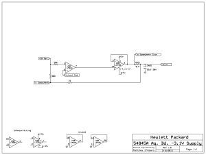
Partial Schematic of the -3.1V supply on the acquisition board of the HP 54845A oscilloscope.
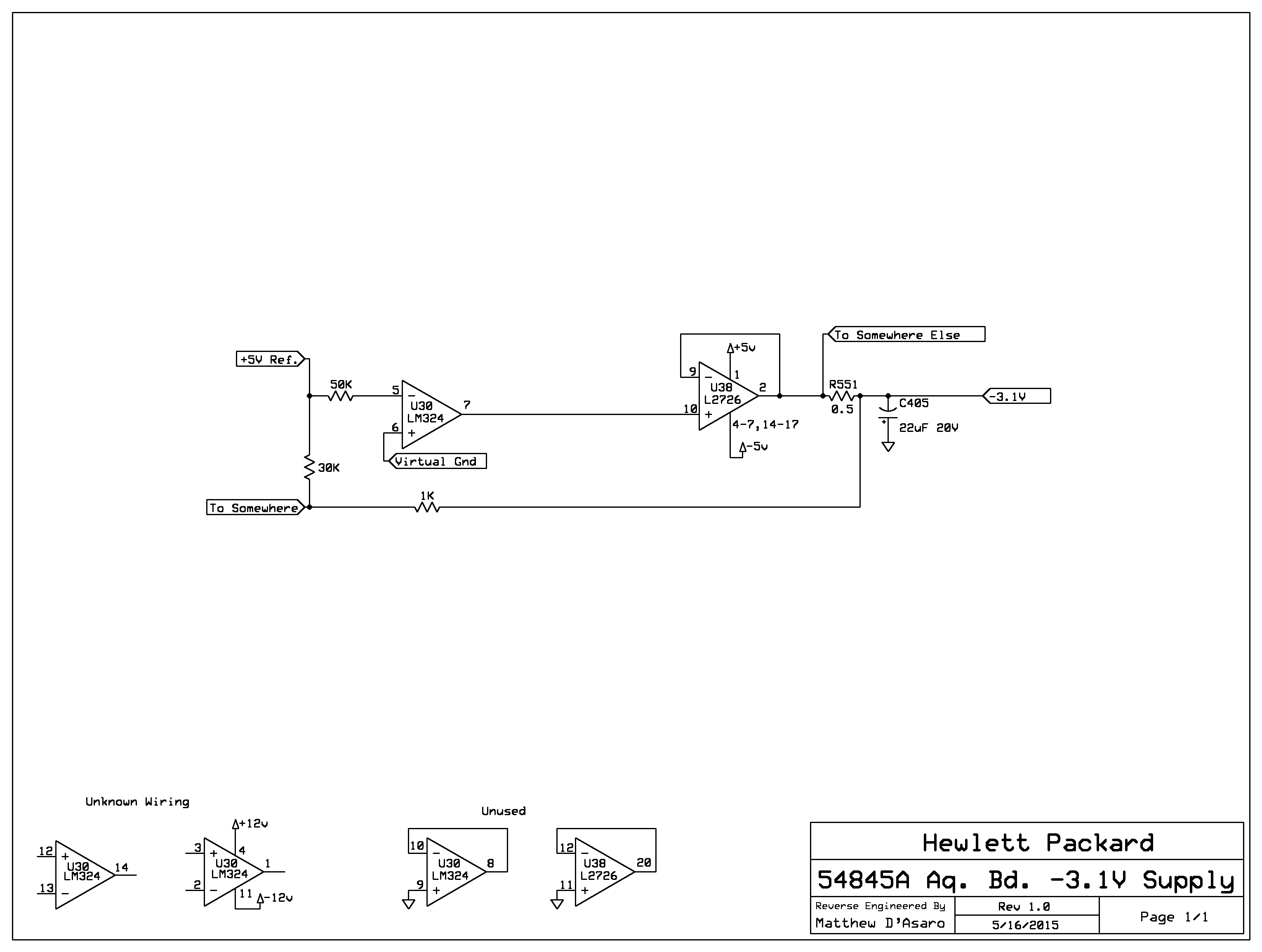
From this schematic, it became obvious that the L2726 had an extra, unused opsmp in it of the same type as the questionable one. This enabled me to do a bit of quick-and-dirty solder work to swap them electrically. When I tested the supply with the unused section connected, it could deliver a full amp without sagging or going positive! After all that, the problem was just a bad opamp! The photo below shows the jumper wires used to connect the extra section.
Failed U38 opamp with the good ‘spare’ section wired in place of the bad one.

The reason that the supply would get ‘stuck’ positive after being loaded was as follows. With U38 being wired as a buffer, its only function is to supply current. The supply regulation is accomplished by U30, an LM324. When U38 failed, it did not do so completely, rather, probably due to electromigration, its output devices stopped being able to supply more then a few mA of current. Thus, when it was loaded its output would start to droop. When this occurred U30 would pull the non-inverting input of U38 more negative to try and compensate. However, with U38 totally unable to supply any more current, this did nothing, so U30 continued to drive U38’s non-inverting input negative until U30 railed at ~-10.5V. The problem, though, is that this is more negative then the -5V negative rail of U38! When an opamps inputs are driven beyond the rails the behaviour is unpredictable (it depends on the details of the specific opamp being used) and in this case it causes U38 to try to drive its output POSITIVE! Thus, a positive feedback loop is established where U30 tries to drive U38 negative and by doing so actually drives it positive, thus latching the system until the power is cycled. In short, replacing U38 totally solved the problem.

Replacement U38 (L2726 opamp) installed, but before the heatsink was reinstalled.
At this point, I was able to reinstall both attenuator assemblies without any extension cables and verify that all functions of the oscilloscope worked correctly and that it would pass its self test, which it did.
All that was left to do, then, was to give the whole thing a good cleaning, lubricate the noisy CPU fan (if you take the sticker off the back of a noisy computer fan and apply a drop of synthetic motor oil to the bearings they usually work fine again), reinstall the missing Q2 in the dismantled attenuator assembly, and put the shields back on. Before I did this last item, though, I spent some time finishing my reverse-engineering of the attenuator connector pinouts. Hopefully this information will help the next person who runs into some similar problem on one of these beasts!
Left connector when looking at front of scope, J7 on attenuator module, J7 or J9 on acquisition board:
| Function | Pin # | Pin # | Function |
|---|---|---|---|
| Gnd | 26 | 25 | Gnd |
| Gnd | 24 | 23 | Trigger Signal Out |
| Gnd | 22 | 21 | Gnd |
| Bias current source for hybrid. ~0.7V with attenuator module installed or 3.3V without | 20 | 19 | Preamp gain – low = x1 high = x2 |
| Offset DAC Digital Data | 18 | 17 | +5V (Hybrid Digital) |
| +3.9V (Hybrid Analog) | 16 | 15 | +5V (Impedance Converter) |
| Gnd | 14 | 13 | -5V (Impedance Converter) |
| Gnd | 12 | 11 | 1M Path Guard Voltage |
| K1 Relay Coil #1 (1M x10 attenuator) | 10 | 9 | K1 Relay Coil #2 (1M x10 attenuator) |
| 1M Path Low Frequency Signal Components Out. +1.8V in 50-Ohm mode | 8 | 7 | 1M Path Self Calibration Signal In?? Normally 0V with attenuator installed. |
| K4 Relay Coil (50-Ohms x5 attenuator) | 6 | 5 | 1M Path Low Frequency Signal Components In |
| K2 Relay Coil #1 (50-Ohms/1M) | 4 | 3 | K3 Relay Coil (50-Ohms X10 attenuator) |
| Input Voltage Sample for Protection Circuit | 2 | 1 | K2 Relay Coil #2 (50-Ohms/1M) |
Right connector when looking at front of scope, J8 on attenuator module, J6 or J8 on acquisition board:
| Function | Pin # | Pin # | Function |
|---|---|---|---|
| Gnd | 26 | 25 | Gnd |
| Trigger Signal Out | 24 | 23 | Gnd |
| Gnd | 22 | 21 | Gnd |
| Bias current source for hybrid. ~0.7V with attenuator module installed or 3.3V without | 20 | 19 | Preamp gain – low = x1 high = x2 |
| N/C?? | 18 | 17 | Gnd |
| 1M Path Guard Voltage | 16 | 15 | Gnd |
| +6.3V (Hybrid Analog) | 14 | 13 | Gnd |
| -3.1V (Hybrid Analog) | 12 | 11 | +3.9V (Hybrid Analog) |
| K5 Relay Coil #1 (1M x10 attenuator) | 10 | 9 | K5 Relay Coil #2 (1M x10 attenuator) |
| 1M Path Low Frequency Signal Components Out. +1.8V in 50-Ohm mode | 8 | 7 | 1M Path Self Calibration Signal In?? Normally 0V with attenuator installed. |
| K8 Relay Coil (50-Ohms x5 attenuator) | 6 | 5 | 1M Path Low Frequency Signal Components In |
| K6 Relay Coil #2 (50-Ohms/1M) | 4 | 3 | K7 Relay Coil (50-Ohms X10 attenuator) |
| Input Voltage Sample for Protection Circuit | 2 | 1 | K6 Relay Coil #1 (50-Ohms/1M) |
Note 1: Except for power supplies and digital, all signals are for one channel (1/2 or 3/4) only.
Note 2: All supplies are stable and accurate with the attenuator modules removed except for the +3.9V supply.
Note 3: The 1M path is weird in that the high frequency signal components are amplified in the attenuator module, but the low frequency components are amplified on the main board in a circuit which also handles AC coupling and offset. See page 8-7 of the service manual. The DC bias of both the low frequency components in and out pins varies with the offset control. With the attenuator module removed, the ‘out’ pin will clamp at either ~-9V and ~+9V depending on the polarity of the offset. The ‘in’ pin various smoothly with the control independent of whether the module is installed.
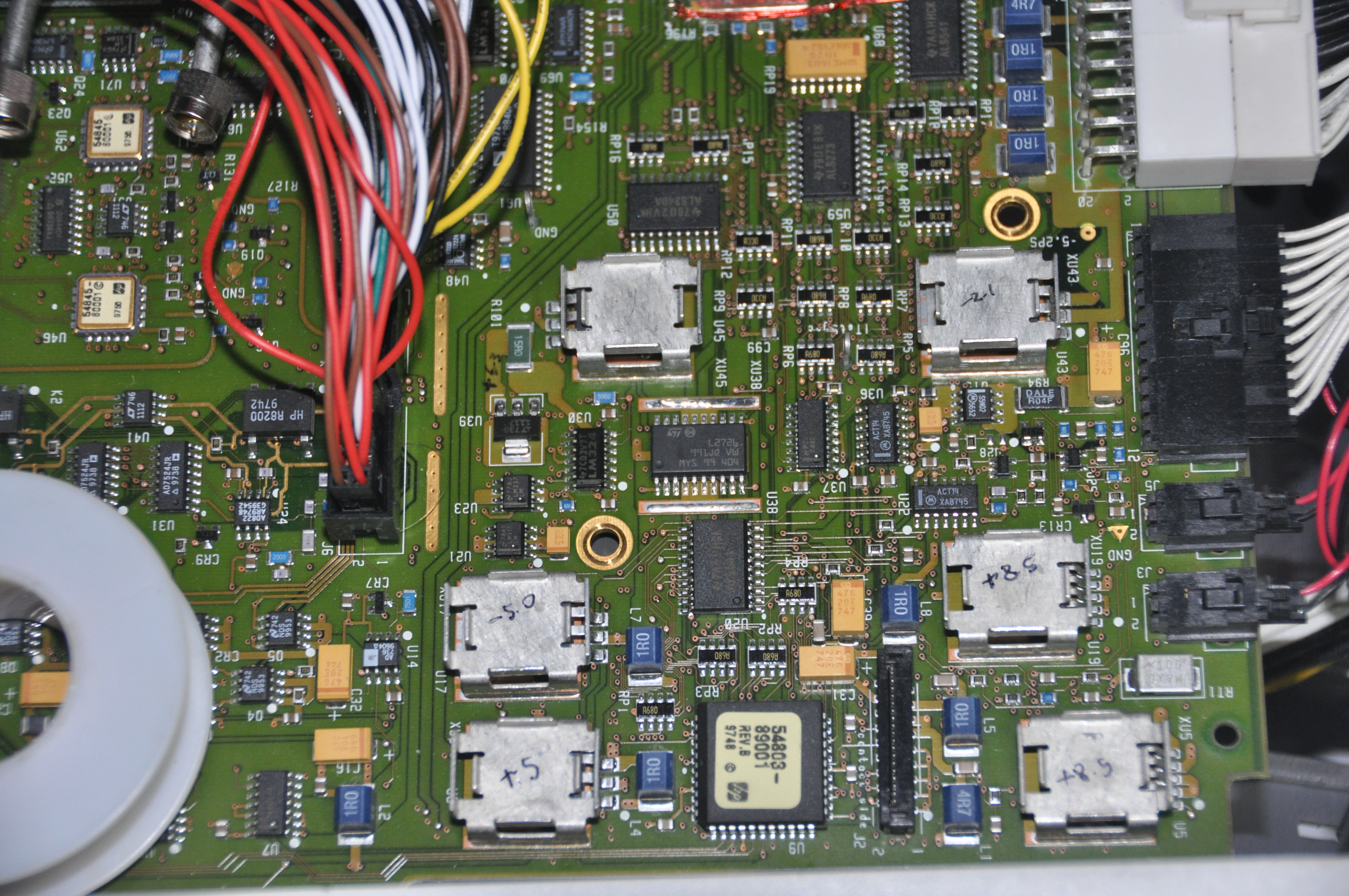
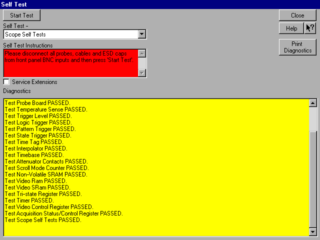
After getting it all cleaned put back together, I ran the self test again. It passed! Then I verified the bandwidth (as best I could with the equipment I had) for both the 50-ohm and the 1M paths. Good again. Then I ran the self calibration, and wala! It passed that too. Wow! it Looks like I have a working 1.5GHz oscilloscope!
It passed its self test!
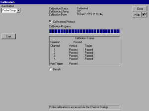
And it passed its self calibration!

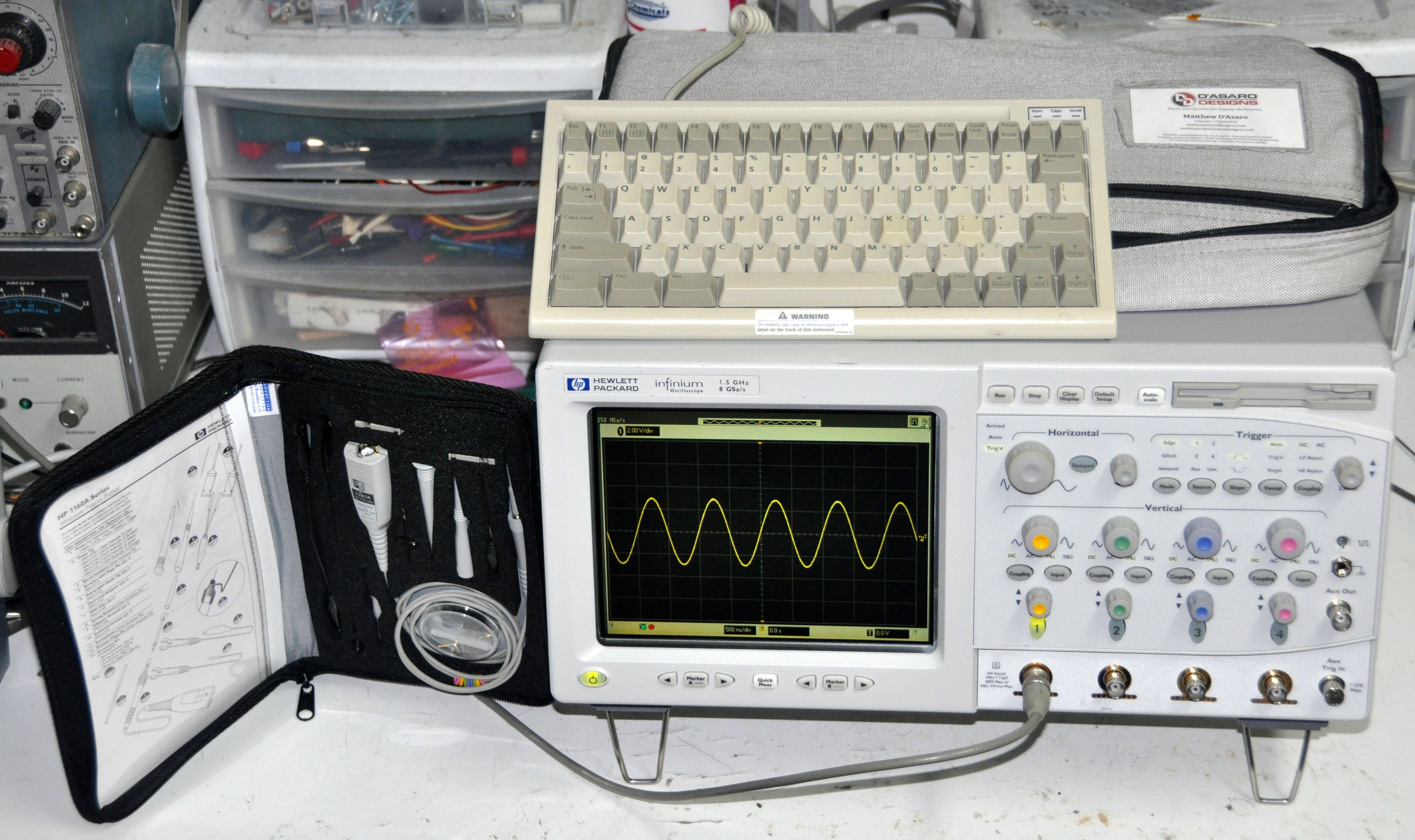
Finally, here it is with the correct miniature keyboard and new HP branded 1161A probe I bought for it. I was even able to find a power cord in my collection with a hang-tag indicating that it was an official HP one of the correct part number for this scope! I am still looking for three more HP branded 1161As to complete the set, but other then that I am pretty happy to day that I have a ~$2000 oscilloscope for $240 (plus countless hours of my time, but, oh well, it was fun!)
Here it is – all set up and working.
That’s all folks!
-Matthew D’Asaro
Matthew, you never fail to amaze me with your projects. And the superbly well written instructions that will help others in the future. Cudos.
Hello
I have read your article.With compliments
I’m reparing an Agilent HP 54810A that mount ( I think) a similiar power supply.
This is fault and it’s impossible to repair it without schematics.
Have you the schematic circuit of the power supply?
Best regards
Massimo
Sorry, but I don’t have any schematics for the power supply. That said, I think the main power supply is a pretty standard switching supply – it shouldn’t be hard to work on even without schematics.
-Matthew
A job well done, Matthew!
I have an Agilent 54810A that passes almost all self-tests except that Gain Test failed on both channels 1 and 2. Based on your experience with repairing 54845A, I wonder if this is due to faulty attenuators and whether this can be repaired.
Please advise!
Thank you so much
Thank you for the comment. I believe that the 54810A is quite different internally from the 54845A, so I am not sure how much of my experience with the 54845A is going to apply here. In general when troubleshooting a problem like that, I would apply known-amplitude signals and try to determine exactly how much the gain is wrong by and on what ranges. If it is range-dependent then it is certainly the attenuator and should be pretty easy to track down. If not it is harder…
-Matthew
Great job !
Congratulations !
Regards / Roumen
LZ3RV, Sofia, Bulgaria
You write: K4/K8 (datasheet) are x5 50-ohm attenuators.
It is A150 Teledyne.
I could not find x5 (14 dB) in its datasheet.
Please comment
Thanks
Thanks for the comment. It is indeed true that the 14dB value for the A150 is not listed in the datasheet. I assume that HP/Agilent had a custom value made for them. This practice is really common in other HP parts at least. It is also possible that the attenuation value is not exactly 14dB – I did not attempt to measure it but rather went off of what was specified in the theory of operation section of the service manual.
I’ve been thinking about buying one of these scopes used but have concerns about the availability of parts if some need to be replaced. If you had not been able to repair it, what are the options for replacement parts? Do you pretty much have to buy another donor scope? Also, now that the scope is repaired, are you going to get it calibrated? And are there companies out there that still do calibration on scopes that old? I checked with Agilent/Keysight but it looks like they don’t do it anymore. Finally, have you run into any situations where the slow waveform update rate (~2000/second) or lower memory depth has hampered the usefulness of the scope?
Overall, I like the 54800 series scopes. I’m willing to spend a few thousand $ for a decent one but it has to be dependable and produce accurate measurements.
Thank you for your comment. I will attempt to answer your questions one at a time. First, I know of no source of replacement parts for this oscilloscope except a parts unit. Even then, I was outbid on eBay multiple times at over $700 for parts oscilloscopes of this same model. As for calibration, that is not needed. It has its own internal self-calibration routines. If I recall correctly, you need to check an internal voltage refernece and an internal frequency reference and it calibrates everything else from these. As for the slow waveform rate and low memory depth, I will be frank with you. I have hardly used this oscilloscope since I fixed it because my handy Tektronix TDS3034B does 99% of what I need. The only cases where I have really needed the bandwidth on this thing have been looking at the output of a tunnel diode pulse generator and measuring the rise-time of a line driver chip. In both cases, the depth and waveform update were not an issue. If you plan on attempting to capture digital data with this thing (really, just use a logic analyser), or looking at analog signals with both low and high frequency components then absolutely, these would be limitations, but for more general work it is probably fine. If what you want is dependability, I would probably look elsewhere. Although I have no hard numbers for you, based on the number of these things that go by on eBay with at least one problem, the high temperature at which they operate, and the complexity of their construction, I don’t think it is the most dependable oscilloscope. It is a Ferrari – not a Honda Civic.
Hey thanks for the speedy & thorough reply. I mainly need the high speed for checking fast edge rates on switching power supplies. Of course, to get the full capability, I have to spend about as much on differential probes as what a decent scope costs :-(. I hear you on the Ferrari vs Honda analogy. I think I’m going to look into leasing a new scope for now.
-Thanks
Hola, la tension en el u38 debe de ser de 3,3v, justo debajo del circuito integrado al lado del u38 hay una resistencia de 6k que se suele devaluar, esto hace que la tencion no este estable y el trazo no se situe en el 0
Great article and informative as well, I fixed a hp 54610b scope, it was a faulty preamp attenuator.
Are the voltages you marked on the pictures the all voltage measured on the heatsink? The ones I measured on mine mostly matches that, the ones that doesn’t match does have one pin with the voltages you mentioned.
XU43 (heatsink of the 3rd chip from the bottom of the right side of the picture) measures -5.17 but its rightmost pin of U43 measure -2.1.
XU38 (heasink of the L2766) measure -5.1
XU17 measures -12.16 but the rightmost pin of U17 measures -5
XU19 and XU5 both measures 17.5, but both of the rightmost pins U19 and U5 measures 8.6.
Do you think they are normal?
I got a weird problem that my scope passes everything, but cannot cal channel 2,3,4’s vertical only (trigger cal passes). I swapped the attenuators, nothing changed (Ch1 still passes and the rest fails vertical).
I swapped the large IC called “HP R8200” under the attenuators of Ch1 with Ch2, but it still Ch1 passes cal but Ch2 doesn’t, so it rules that chip out. I reloaded the Windows 98 and noticed the uncalibrated trace of Ch 2,3,4 went off screen. The failed calibration brought them back to the center, so I suspect something along Ch2,3,4’s signal path is way off specs and there aren’t enough software correction margin to pass the cal.
Any ideas?
First, thank you for the note. I am glad you enjoyed the article. Second, the voltages are shown on the heatsinks only because it was a convenient background to display the text on. The voltages refer to the outputs of the regulators, whatever pin that happens to be on. Sorry, I should have made that more clear.
Your problem sounds to me like it could be damaged ADC hybrid(s). Have you tried swapping these around and seeing if the problem moves with them? They are just screwed in so this is easy to do.
Good luck!
-Matthew
Thanks. That’s what I thought too, but I’d confirm with you on the safe side just to make sure I left no stones unturned.
I actually have half a dozen spare ADC hybrids lying around. Swapping them in any combination doesn’t change a thing. That’s what’s puzzling, as it passes everything and the signal looks fine on the scope (after the failed calibration) for every volts/div (I verified them turn by turn).
You marked the voltage of L2726 as -3.1V, but it’s an op-amp. Since it’s negative, I’d assume you are not referring to the supply rail voltage. Since that chip has many pins, I haven’t got a chance to remove the heatsink to probe it. What could the -3.1V be?
Thanks for blogging about the repair. As you said, it’s a Ferrari. To me, restoring it is more fun that driving it.
I had a quite elaborate home lab when I was in grad school, but had to chose between taking it down / moving out when my last assigned roommate didn’t like the geeky feel I added to the living room. Lucky you!
Per the partial schematic in my post, the -3.1V supply output is on pin 2 of U38, the L2726 opamp. This voltage is used by the attenuator / preamplifier modules as the negative supply rail.
I would recommend your next step to be resetting the calibration by reinstalling Windows (as you did before) so that the traces are off screen. Then, try injecting a signal directly into the ADC module from a signal generator. Is it on screen? If so, measure the output from the attenuator / preamplifier module. Does it have a large offset? This will allow you to narrow the problem.
-Matthew
Yup mine turns out to be -3.3V for the L2726, so it should be fine.
I just cleared the calibration to send the traces of Ch2,3,4 off screen (don’t need to reinstall windows, the cal files are under C:/scope/cal) and injected the a 500kHz signal into Ch2 with varying amplitude and offset, up to 5V. It’s still way off the screen so I couldn’t see any signals.
Just out of curiosity, I redirected Ch1’s attenuator to Ch2’s ADC (and vice versa) with some SMA cables. Playing around with the Ch2’s offset dial physically offsets the signal in the path “Ch2’s attenuator -> Ch1’s ADC”.
So I guess the attenuator of Ch2 is capable of injecting a true electrical offset. Nonetheless, no matter how I move the dials for Ch1 attenuator -> Ch2’s ADC, nothing show up in Ch2. Still off the screen.
Hi Matthew.
I work at the university of Illinois at Chicago and we have the 54845a scope. We have had a hard disk failure and Keysight cannot help us. Would it be possible to get a image of your hard drive. I know it is a long shot but right now the scope is useless to us.
don
Thanks so much for your question. No problem on the disk image – I already saved a backup when I worked on my scope. You can download a copy here. Note that you will need a Linux box with dd or some similar raw bit-for-bit cloning program (like WinImage) to restore the backup. Enjoy!
-Matthew
Hi Matthew.
You are fantastic. Thanks so much I really cannot thank you enough, I will try to write the image as soon as get a drive.12:01
Thanks for sharing! (I have not checked if you got the XP or win98 image yet) I needed this too, but first I need to repair the psu. For a long time I have been needing to “double power” (push once, push and hold until fans stop, then push again) to get it running , but now there is just a smps hizzing sound. Checking all caps ofcourse. No result yet.
Thank you for all your hard work. This information was very helpful and my scope is now up and running! I’m looking forward to using it on my PDP11 restorations and antique radio and test equipment projects. A barn full – lol!
Very cool! I am so glad I could help. Good luck with your other projects – I have a PDP-11 as well which I am in the process of restoring. I may post an article on it when I am done.
-Matthew
Congratulations on completing your project and I am really glad to hear my hard work was was useful to you. Good luck on your vintage computer restorations – I have a PDP-11 as well that I am working on restoring. Maybe I will post an article on that project when it is done.
-Matthew D’Asaro
Good Morning,
I am sorry to keep bothering you. I wonder if you might have insight as to why I get the message Invalid System Disk when I try to boot 54845a scope from a disk that I made from your disk image. When I compare your image to the disk that I created, I get no error message. I can mount your image and it seems to be identical to the mounted disk. The disk starts to boot on a computer halts with a message insufficient memory.
Thanks again for the disk image and any insight that you might have.
don
Don’t worry about bothering me – this is an interesting project. First, good job tracking down a disk and getting the image transferred to the disk. The fact that the disk starts to boot on another computer means that you most likely got the image transferred correctly. I am not too worried about the memory error – that is most likely due to the motherboard on whatever computer you booted the image on being different from the hardware in the scope. I have seen Windows 98 can give “insufficient memory” in this situation before. The more interesting question is why the scope is not recognizing it as a valid system disk. The most likely reason I can think of is a BIOS setting problem or that the disk you found is too new to be properly recognized by the system. I would recommend carefully checking all the BIOS settings (maybe reset them all to factory defaults first) and trying again. If that does not work, boot the system off of a Windows 98 boot floppy (you can download an image online if you look) and see if you can see the contents of the hard drive when booted off of the floppy. If not, you know that the system is not recognizing the drive correctly.
If none of this works, answer the following questions in your reply:
– What are the capacities and model numbers of the original and replacement drives
– What software did you use to copy the image
-Matthew
Hi again,
When I boot off of a floppy, I can see the hard drive. It has 6 files(131,724 bytes) and 11 directories. I bought a used IBM Travelstar DJSA-205 and is 5Gb, which is what was in the scope. I ran a badblocks on it and found no bad blocks. I used the command
sudo dd if=54810-83512.bin of=/dev/sdc.
Thanks for the really great help.
don
OK. Odd. It looks like you did everything right – same model hard drive, correct command to copy the image, and the disk does show up in DOS. A couple more questions. Did you make sure to set the master/slave jumpers on the new drive to the same position(s) as the old drive? Also, did you try resetting the BIOS settings. Also try disconnecting the internal CD-ROM drive (if present) to see if that makes any difference.
-Matthew
Hi Matthew,
The original drive had no jumpers nor does this one and uses a 44 pin cable. I set the bios to defaults and will try some others. The unit has no cdrom as far as I can tell. The bios does recognize the drive as the primary master and dos found it as the C:\ drive.
Thanks
don
Very, very odd. The next thing to try is to format the hard drive from within DOS while booted off of the floppy. You can first try a “sys c:” which will attempt to flag c: as bootable. If this does not work, do a “format c: /s” from the floppy disk and then see if the scope will boot from the hard drive. Of course, this will erase the image you currently have on the drive so you will have to copy the image back on the drive when this test is done. However, this will tell us for certain if the reason the system won’t boot is because the image is damaged or if it is a hardware / BIOS issue. Good luck.
-Matthew
Hi Matthew,
You are amazing. I know I should have thought of the sys command but fdisk said that it was bootable and I quit after that. I would never have gotten the scope working without your image and HELP AFTER THAT. I cannot thank you enough.
don
I am so glad you got it working! Congrats! I am glad I could be of help. It still puzzles me that the disk needed to have sys run on it since the bit-for-bit image should have resulted in an identical disk. I guess I will have to try making a disk for myself and try it in my scope to know for sure. In any case, you got it working and anyone else reading this now knows how to do it too.
Matthew
I fixed the”Invalid System Disk” by trying each of the 3 choices for found in award-bios ide-autodect for disk-geometry (cylinders, head, sectors). The setting that worked was 2nd one, and it did *not* match they cyl/hd/sec on the printed paper label of the oem 2gig IBM ide laptop disk. I added the right settings to label.
I was pre-emptively replacing the mechanical IDE drive with a transcend-ide-ssd, and tried 3 different disk-imaging methods: ghost, dd, and partimage. I also want to try a ide-to-msata-ssd to be most future-proof.
At first the SSD gave “Invalid system disk” until I found the right cyl/hd/sec values.
Eventually, maybe with “sys c:” or “fdisk /mbr”, I eventually got the ssd to boot with the bios settings for 32gig ssd-ide disk on AUTO/AUTO (instead of specific cyl/hd/sec values). That way, If cmos battery dies/ needs replacing, then disk settings will likely revert to same AUTO/AUTO, and it should still boot.
I never reset the bios to factory defaults, at least without first recording the bios settings. Especially as my scope had an ancient HP isa gpib-card which might require certain irq/int reservations. I have some clear photos of each bios screen I plan to post somewhere, along with step-by-step.
At one point I also decided to create the dd with the oem-disk still in the scope, so I connected a ide-cdrom and booted puppy-linux 4.3 which runs on 64meg of ram. (I added a grub4dos bootmenu item to let me dual-boot the scope to win98 or puppy-linux without needing the cd.) We also have a similar older scope that runs win95 on 16meg of ram. To make a backup image of that without opening the scope I was able to map a drive-letter to a net-beui share on xp-box, and ghost it similar to:
http://pdub.net/projects/agilent-recovery-cd/
Under 10 minutes to create ghost image. TinyCore linux might work on 16meg of ram also.
The reason I create the dd image with the drive in the scope is to try to avoid the boot problems that have to do with how the bios assigns geometry. I recall similar trick, when replacing/upgrading a ide-laptop drive. If you take the old drive out and image it, sometimes the new drive would not boot. Trick was to leave the drive in the laptop and image it, for example, to new drive connected via usb. Then put new drive in laptop and it would boot. The whole issue of drive geometry dependencies in the boot loader was a black box of black magic.
Thanks so much for posting all of this useful information.
-Matthew D’Asaro
Hi Matthew
I have a similar scope, a 54831B. I managed to blow channel 1 by measuring a 300V signal 🙁 Even though I used a 10:1 probe, channel 1 has now a strange offset. It still kind of works, but it looks like it has a permanent AC coupling (DC coupling not possible).
The scope passes all self tests except the preamp test. Do you think this could mean the hybrid is blown? The failure is definitely only on channel 1. I opened the assembly and found out that it looks pretty similar to yours, using also a hybrid which looks like that one in your pictures. But for the moment I have not yet an idea how to fix it 🙁
Best regards,
Tobias, HB9FSX
Yep. Sounds like a bad hybrid, unfortunately. Look for another attenuator board – I don’t know of any other way to fix this.
-Matthew
I have the one of the same series (54815A, 500MHz, 1GSa/s) which I bought “junk” because it didn’t boot. The reason was simply because dead cmos battery. After it booted I found out that channel 4 is offsetted very high. Even at 50v/div I still can still see that the trace stuck at the top of the screen. The 3 other channels are working fine tho.
Maybe someday I’ll take it apart again and see what’s wrong with it, as maybe mine has the same symptom as yours. At least on only one channel.
Do you know how to change the CMOS battery in the motherboard of 54845A ? I dont see a CMOS battery in motherboard. I see one in the one of the plugin cards, probably the data-acquistion card. Thank you in advance.
The CMOS battery is actually inside the Dallas 12887A clock module. It must be unsoldered from the board and replaced as a unit (some might be in sockets), but replacements, in the form of new DS12887A+ parts, are widely available from Mouser, DigiKey, etc.
-Matthew D’Asaro
Dear Matthew,
We had the same problem with our infinium and thanks to your guidance we were able to fix the problem today, by replacing the DS12887A. Some preliminary checks show that everything works fine, we will calibrate it on Monday to see for sure. We are really grateful to you for your help!
If you got it open, clean contacts in asic socket (tho he does not say or show how). See:
TSP #79 – Teardown & Repair of an Agilent 54845A 1.5GHz 8GS/s Infinium Oscilloscope
(It’s a win95 model, and you can see disk-geometry on the bios-screen during boot).
https://www.youtube.com/watch?v=GbKfZ4WWt4k
my 54845a power supply not work . i need pinouts and schematic
Sorry, I don’t have any schematics nor can I offer any repair services for the foreseeable future.
-Matthew
amazing job. I enjoyed reading the whole thing. Nicely done!
Now I feel a strong urge to buy a broken 54845A 😉
Hi Matthew,
First of all thanks for the elaborate description of your repair project, you really have provided a lot of useful information for anybody who needs to repair this scope model.
My scope had a bad ADC Hybrid on channel 3 so I replaced this with a working one, and now all 4 channels will show a trace, although the traces of channel 3 and 4 have a slight offset of about + 250mV.
But the scope self test fails for all the trigger events (Pattern Trigger; State Trigger; Trigger Level and Logic Trigger).
I checked all the Voltage regulators and except forXU5 and XU19, they all match the values you have listed.
XU5 and XU19 measure respectively +7.09V & +7.12V instead of +8.5V, but I don’t think that this interferes with the scope functionality, because it looks that they only supply power to the two large cooling fans.
I have checked the attenuator connector pin-outs, and there some differences with the values you have listed.
J7 & J9:
Pins 20: (+ 1.61V with attn installed); (+1.71V w/o attn installed)
Pins 16: +0.845V
Pins 8: (-2.78V with attn installed); (+1.8V w/o attn installed)
J6 & J8
Pins 20: (+ 1.61V with attn installed); (+1.71V w/o attn installed)
Pins 8: (-2.78V with attn installed); (+1.8V w/o attn installed)
Pins 11: +0.845V
Pins 16 from J7 & J9: and Pins 11: from J6 & J8 are all fed from the same regulator U45 which is an LT 1086.and is set at + 0.85V, so how can it be that you measure +3.9V? on pins 16 & 11? (did you measure against ground?
Please let me know your thoughts
Regards
Sorry. I didn’t troubleshoot the trigger circuit much and don’t have much insight into how it works. I would offer to make some measurements but I no longer have my lab setup after I moved to Seattle to take a new job. Good luck with your project.
-Matthew D’Asaro
Nicolaas,
Any solutions yet ?
Same issues here.
Helen
Hi Matthew,
I recently picked up an Agilent 54845a from auction, and everything seems to function just fine during use. In addition, self-tests all pass, but during self-calibration, the verticals for all channels pass, but triggers fail for every channel. Aux trigger passes. I don’t have a real good understanding of what is being done during this procedure; could you possibly provide an explanation of what the exact issue is (what the scope is looking for and not getting), and provide any tips on how to correct this? Thanks so much.
Sorry. I didn’t troubleshoot the trigger circuit much and don’t have much insight into how it works. I would offer to make some measurements but I no longer have my lab setup after I moved to Seattle to take a new job. Good luck with your project.
-Matthew D’Asaro
Hi Matthew,
It is the assembly with the BNC probe connectors. Thanks.
Nadim
As I recall, it is just held on with little metal clips. I slid a screwdriver under the edge and it pulled off the front of the machine. However, it has been years and I don’t really remember, so don’t take my word for it. There might be screws or something. In any case, I don’t recall it being difficult to get off.
-Matthew D’Asaro
Hi Matthew: Impressive troubleshooting and repair on your scope and a great write-up!! I just bought one of the same from a surplus dealer who said it powered up but failed to boot. I cleaned it up, made sure all cables and such were plugged in correctly and tried to fire it up only to see smoke rise from the rear. Turns out what looks to be an SMD cap smoked on the SVGA board; no idea what value or if it is even a cap as it is totally destroyed. Also most of the electrolytics on the motherboard are bulging and some are leaking and/or shorted. I’ve ordered new electrolytics to replace those, but was wondering if you can tell me what the SMD component and value on the back of the SVGA card is. It is located just below the ~1/4″ hole and above the edge connector closest to the output end of the board and one end is connected to a trace that routes to J101 (haven’t checked for the pin # yet). Appreciate you taking the time to reply.
Regards,
Rick
Thanks for the message. The attached photos front and back should help you identify the part.
-Matthew
Great write-up. How did you pull the auto-probe assembly? Thanks.
Regards,
Nadim
Thanks for the comment. I don’t know what you mean by the “auto-probe assembly”
-Matthew
Hi I have a 54825A it reports cmos battery low and only boots to F1 for set up or F2 for defaults , it was working ok the other day.
Where in the scope is the battery and what is its voltage ?
Do you have a part number for one , or where can I get one.
If I replace the battery will the scope boot up ok
Please help
The battery is integrated into a DALLAS RTC module. It must be replaced as a module. Here is a nice article on replacing one in a similar oscilloscope:
https://www.existingwheel.com/2017/01/08/agilent-hp-54820a-oscilloscope-battery-real-time-clock-repair/
-Matthew
Hi I have a HP scope 54825A it has been ok but now on boot up reports cmos battery low and says F1 set up F2 load defaults , where is the battery in the scope , what is its voltage and where can I get one, if I replace the battery will it work normally , please help
Hi Roger: I have the same problem with our 54845A, it is not booting-up, F1-F2 load defaults and and CMOS battery low. In this oscilloscope the battery is mounted on a separate PCI card that is an IDE controller. IDE parameters (primary for hard drive) are not save. I replaced the batteries connecting two in series with wires to the board and read the expected 6V at connection points but no luck. Have you been able to get your oscilloscope to work? Thanks, Diego
Are you sure the CMOS battery is on that card? On my oscilloscope, the battery on the card is NOT for the motherboard. The CMOS battery for the motherboard is actually inside the Dallas 12887A clock module. It must be unsoldered from the board and replaced as a unit (some might be in sockets), but replacements, in the form of new DS12887A+ parts, are widely available from Mouser, DigiKey, etc. After that you have to get the HD settings reset right. They depend on the HD and so there is no universal answer. I suggest that you look at the HD label, or if you have a good scope, look at the setting there. Else it is a bunch of trial and error.
-Matthew D’Asaro
Hi Roger:
A few months ago I was able to bring our HP54845A back to life after installing a new hard drive an operating system. Now, I am getting exactly the same error that you report. In addition, the settings for the IDE have been lost (has to be primary) and are not stored after re-setting. I de-soldered the original batteries (2) and connected a new one using extension wires. Still the same problem: CMOS battery low and the oscilloscope will resort to F1 F2 setup. Have you been able to solve this problem? Thanks!
Are you sure the CMOS battery is on that card? On my oscilloscope, the battery on the card is NOT for the motherboard. The CMOS battery for the motherboard is actually inside the Dallas 12887A clock module. It must be unsoldered from the board and replaced as a unit (some might be in sockets), but replacements, in the form of new DS12887A+ parts, are widely available from Mouser, DigiKey, etc. After that you have to get the HD settings reset right. They depend on the HD and so there is no universal answer. I suggest that you look at the HD label, or if you have a good scope, look at the setting there. Else it is a bunch of trial and error.
-Matthew D’Asaro
Matthew, I have the same HP 54845A Scope. I was having the same issues you encountered. I replaced the U38 (L2726) like you said. I went from having no signal at all to having a signal with a gain offset issue. I tried calibrating it. No luck it said offset Dac fail and gain fail when you do the self test. I found on the back side of the same board just underneath the U38 right by the hole for the mounting screw that in the C399 cluster there is a component missing. I am trying to find out what this component is. There is a black un marked component by it that looks like either a diode or a resistor. Then the missing component right at the top by the orange stripe on C399 that is missing. I think this may be my issue as it has a trace back to the L2726 chip on the other side. Any help you might provide would be appreciated as I am so close to getting this fixed.
Thank you ,
Kevin
I am sorry – I really wish I could help you – but I didn’t take pictures of the back of the board when I worked on mine and I don’t want to risk breaking it by taking it all apart to do so now. Are you sure the component isn’t supposed to be missing? You can tell because if it was broken off there will be a jagged edge to the solder pads instead of them being rounded. Are all the voltages correct? Have you tried swapping ADC and hybrid modules around to make sure the problem isn’t with one of them?
-Matthew
Kevin,
Any luck ?
Same issue here.
Have a question, I work at a Naval Calibration lab and we have a number of these O’scopes that just came in because of a boot up problem. Currently when you turn on o’scope it will run through the start up and then cannot find the boot file in the HD and request a boot up floppy disk. When you run system setup, it does not recognize the HD. We had one that was working last week and received the error message CMOS battery low. This week it will not boot up from the HD and is looking for a boot file from the Disk drive. Any suggestion on how to solve this issue?
Thank you,
Jimmy
First, you need to replace the CMOS batteries. The CMOS battery is actually inside the Dallas 12887A clock module. It must be unsoldered from the board and replaced as a unit (some might be in sockets), but replacements, in the form of new DS12887A+ parts, are widely available from Mouser, DigiKey, etc. Second, you need to set the heads/sectors/tracks correctly for the HD in the oscilloscope. The exact settings will depend on the particular HD in there so I can’t tell you exactly what they need to be. Your best bet is to look at the CMOS settings for a working one and copy them down. If that doesn’t work, look at the label for the HD and see if it says on there. Good luck!
-Matthew D’Asaro
hi Matthew,
Were you aware of this document ?
It has some text on testing that points to some of the circuitry, in words, without schematics:
https://www.atecorp.com/atecorp/media/pdfs/data-sheets/agilent-54845a_manual.pdf
Yes, I am aware of that, but it is of virtually no use when doing component-level servicing. Thanks for sharing.
-Matthew
My 54845A is reporting “Fine Interpolator Handshake Failed: Service Is Required” after it is powered on for a few days……solution is to leave it off unless I need it. Service Manual, pg 5-55, it says that I may need to replace the “Acquisition Assembly”? Do you know how to find one of these? I don’t have an older scope to cannibalize.
BTW: this site is pretty cool for fixing these…
Sorry, I don’t have any parts for these. eBay is going to be your only option for a parts unit. Troubleshooting that assembly is possible, but I haven’t reverse-engineered it enough to provide you any real clues beyond what is in this article.
-Matthew
Hi Kevin. I have the same problem on my scope. Did you ever figure out the cause of this problem?
This is really great work, the best Read I have had a long time, if everyone document there work like this, repairing old kit would be so much easier, also if manufacturers provided even half this much info it would be great, but alas they don’t.
Thanks for the compliment! I am glad to see that someone is appreciating all the work I put into this.
-Matthew
Thank you so much for the compliment. I am really glad that my hard work on this has been useful to you and other people.
-Matthew
Could you sell the disk driver to operate this oscilloscope?
Sorry, I am not currently selling products or services. I am too busy with my day job.
-Matthew
Sorry, but I am not currently selling products or services. I am too busy with my day job. I will make an announcement on the main page when/if I am back in business.
-Matthew