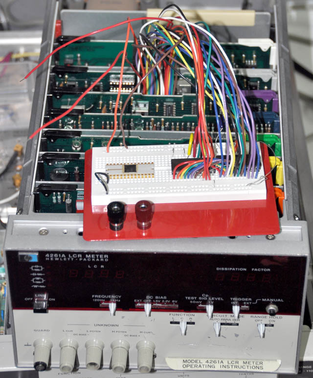
Developing reproductions for the ROM Chips in the HP 4261A LCR Meter
When a (soon to be) customer asked on the HP Agilent Equipment Forum on yahoo for a dump of the custom control ROM chip (P/N 1818-2272A) in the HP 4261A LCR meter, I immediately recognized this as a perfect opportunity to demonstrate my EPROM Programmer Universal Adapter.
Since the schematics for the 4261A are easily available, figuring out how to wire the Universal Adapter to allow it to read the ROM was relatively straight forward but since the ROM has 16 data lines I read it in two pieces. The first contains the data from what I am calling the ‘high data lines’. These are pins 24,6,23,7,22,8,21 and 9 in that order. Just to be clear on the data order, if you were to replace the upper data lines with a standard ROM, you would connect pin 24 to Q0 on the standard ROM, pin 6 to Q1, etc. The second file contains the data from what I am calling the ‘low data lines’ which are 20, 10, 19, 11, 18, 12, 17, and 13, again in that order.
I then repeated the process for the display ROM (P/N 1818-2271A) just so that I would have a backup of both. You can download the images here.
As it turned out, the customer’s ROM was actually bad and a replacement was needed so I burned the images onto a pair of 2716 ROMs, wired it all up on a breadboard, and was able to make my HP 4261A work just fine that way (there was more glitching on the data lines then with the original chip, presumably because the 2716 chips are faster but it doesn’t affect operation as it has all settled down by the next clock edge.) Thus I confirmed that the images are good and that there is nothing special about the original ROM that will prevent it from being replaced with standard parts, so it was on to making the replacement.
I have designed replacements for other obscure ROM chips in the past, most notably for the Commodore PET. However, this case was somewhat unique as the original chip has 16 data lines, thus requiring me to either find a modern 16-bit parallel flash or EPROM or use two 8-bit parts. To complicate matters, the original chip can’t be too much taller then the original or it won’t fit correctly in the LCR meter. This height requirement pretty much ruled out using an old-fashioned DIP EPROM and mandated that whatever parts I find fit easily in the footprint of the original, a 28-pin wide DIP. Looking at the various modern flash and EPROM products, it quickly became clear that the only thing I was going to find in a parallel 16-bit format was EPROM and all of the 16-bit EPROMs that I could find used a DIP or PLCC44 package, neither of which would fit in the footprint of the original. That left me with the option of using two 8-bit EPROM chips. I was hoping to find EPROMs in an SOIC package as that package is the smallest, but although they seem to have been made that way in the past, all the current production parts I could find were in PLCC or DIP packages which I didn’t think would fit. However, after a bit of head-scratching I realized that if I turned a PLCC28 package sideways it would just barely fit between the pins of a wide DIP! Armed with this, I chose the smallest EPROM still in production, the 27C256, and proceeded to lay out a board which would adapt the pinout of the original part to the 27C256’s. I felt kind of bad using only 2KBits of a 256KBit part, but at $1.50 each I could hardly complain.
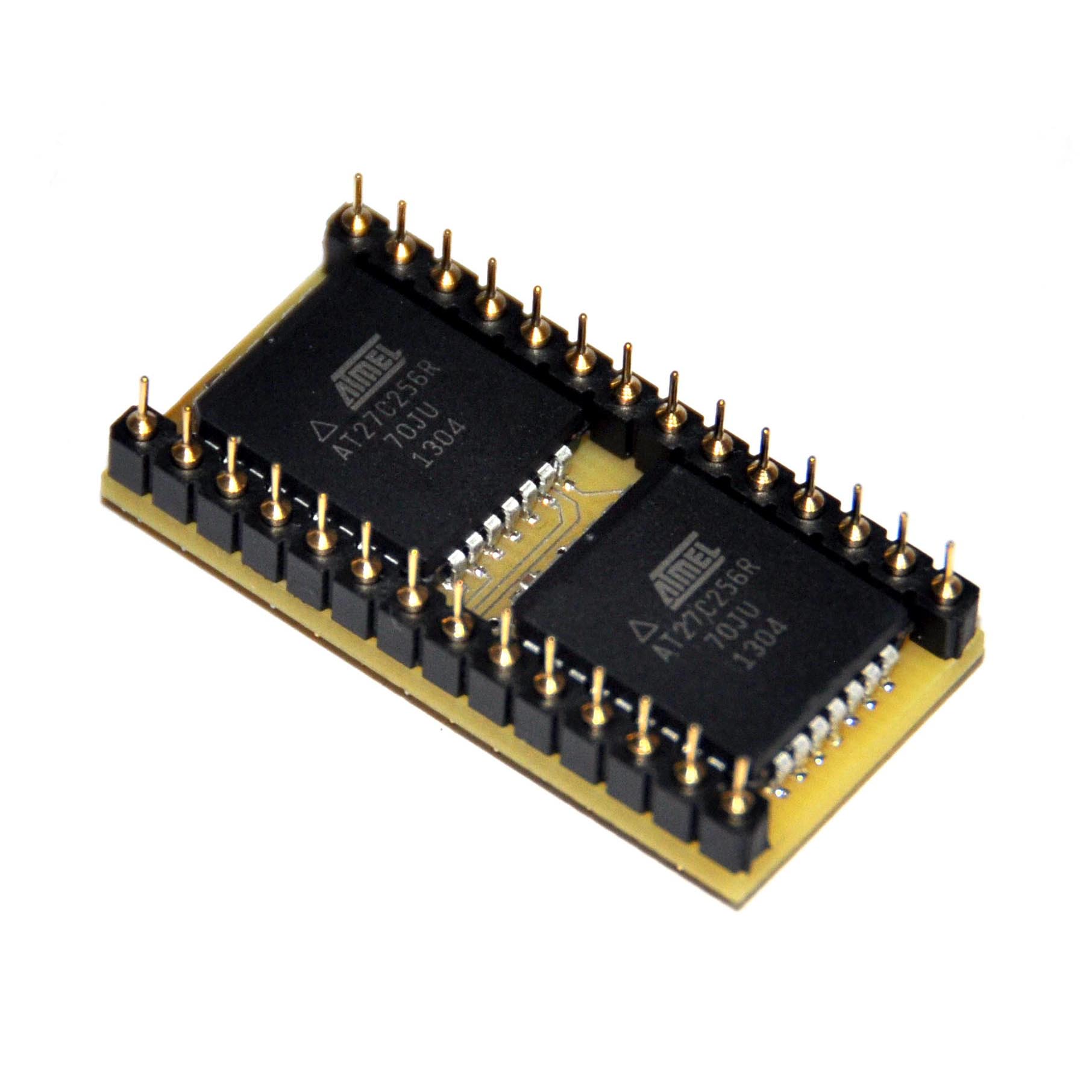
For the pins I chose to use Mill-Max P/N 350-10-164-00-006000 headers which are expensive but are gold-plated like the original pin were and are the correct diameter to use in an IC socket without damage. What’s more, they are just the right height that the EPROM chips can fit under them without running into the board, thus reducing the height of the entire adapter to just that of the PC board plus the chips. All that was left was to lay out the board which turned out to be pretty dense due to the number of pins I was trying to connect in a small area. As a result the power and ground leads got longer then I like so I added an 0.1uF capacitor between power and ground near each of the EPROM chips. After that it was just a matter of waiting for the parts, programming the EPROMs and soldering it all together.
Here is the top of the completed part:
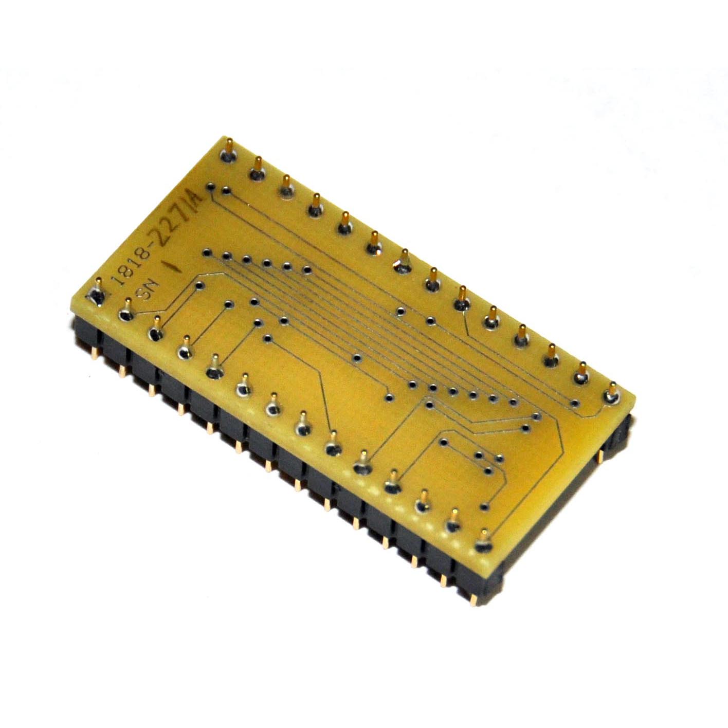
And the bottom:
The new ROM chip fit like a glove and worked like a charm. Here it is installed on the display board:
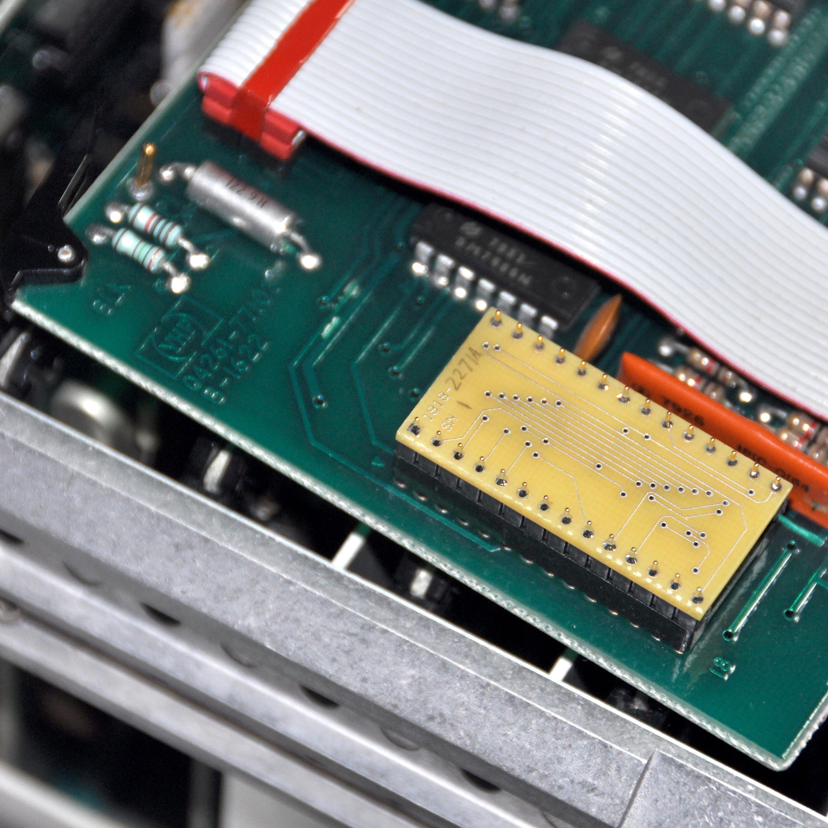
It should be noted that since both the display ROM (1818-2271A) and the control ROM (1818-2272A) use the same pinout my board can replace either one – it is just a matter of the code programmed into the EPROMs. Along the same lines, the same ROM pinout may have been used in other applications meaning that the boards might be able to be used to make replacement ROMs for other types of equipment as well. If you happen to run into another piece of gear which uses the same ROM pinouts, I would be very interested to hear about it.
-Matthew
Note that this post has been modified from:
http://antiqueradios.com/forums/viewtopic.php?f=8&t=226752
The publication date has been modified to reflect the original posting date.
UPDATE 12/21/2015. I received a very helpful and informative note from a reader, Joe Zatarski, who has a very early version of this instrument. Apparently instruments with serial numbers starting with 1545J use a pair two 8-bit 1702A EPROMs in place of the control ROM and the display ROM (four 1702A EPROMs are used in total). He surmises that the EPROMs that make up the display ROM contain the same data as the files in this post, but the control ROM was revised slightly and so the EPROM that make it up don’t match. The change can be seen on page 8-35 of the service manual, figure 8-6, asm chart sheet 6 of 7. He read out the contents of the control EPROMs for this early instrument and you can download the files below. Note that this version was ONLY used in instruments with serial prefix of 1545J. All later models use the version described in the main portion of this post.
Control ROM – 1702A A8, U9
Control ROM – 1702A A8, U8
UPDATE: 5/15/2016. I have developed a whole new version of these adapters. The ones described in this article are now obsolete. Please see the article on the development of the new parts here.
After I initially left a comment I appear to have clicked
the -Notify me when new comments are added- checkbox and from
now on every time a comment is added I recieve
four emails with the same comment. Perhaps there is an easy method you
can remove me from that service? Thanks a lot!
Sorry, I don’t know how to fix this. I Googled it and couldn’t find anything about it. If you can tell me what I need to do on my end I am happy to do it, or even point me toward some article about why this is happening.
-Matthew