A Quick Fix for Tektronix TLA5000 Series Logic Analysers
I was recently tasked with repairing fourteen Tektronix TLA5202 logic analysers, part of a classroom set used for a VLSI class. Although over ten years old at this point, these are still very capable machines and are worth several thousand dollars on the used market, so they are usually well worth fixing. Figure 1 shows what one of these beasts looks like.
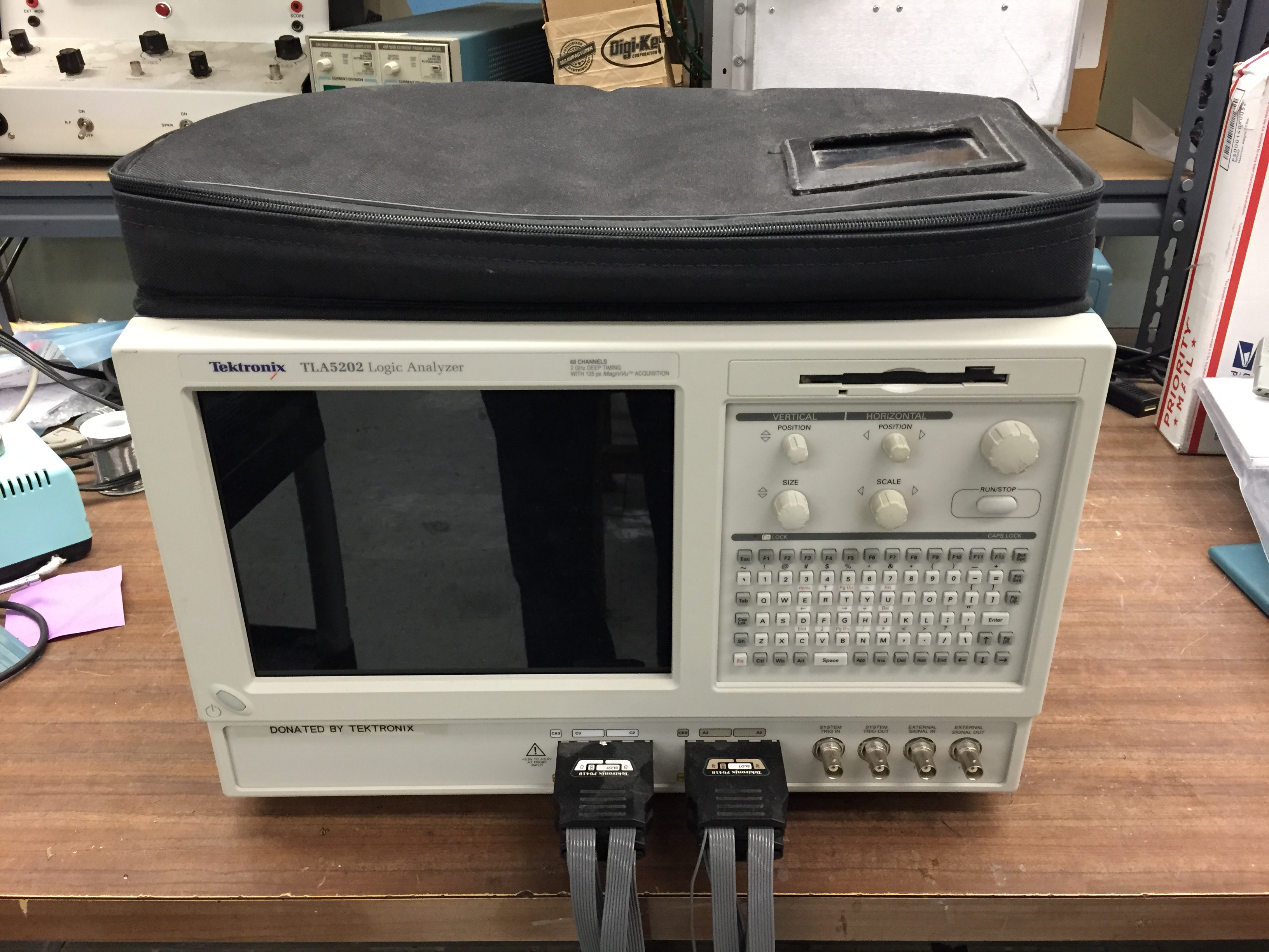
Figure 1: A Tektronix TLA5202 68-Channel Logic Analyser
Although any number of things may be wrong with these beasts, the real Achilles heal, at least in the ones I have worked on, appears to be not any of the proprietary Tek parts, but rather the embedded desktop PC. Specifically, these beasts use a generic Intel D865GLC Pentium-4 class Celeron micro-atx motherboards which, like any ten year old PC, are not holding up to the test of time well. Unfortunately, they can’t be easily upgraded with another generic micro-atx board because:
- The ports of any replacement would have to match exactly to fit into the case
- It appears to use a semi-custom BIOS. At least Tek inserted their own startup screen
- The logic analyser communicated though a PCI slot, so any replacement would have to have an original PCI slot in exactly the same mechanical location.
Since it is a generic PC motherboard, the Intel D865GLC can still be easily found on eBay. If you purchase a replacement, I recommend swapping the BIOS chips so that the original Tektronix BIOS is preserved (see Figure 2). However, in most cases an outright replacement of the motherboard is not needed. In all, I have only replaced one motherboard and that one had a bad connection between the motherboard and the CPU socket, probably due to a fractured BGA balls. See the end of this article for more discussion of this problem.
The most common symptoms of a motherboard problem is a logic analyser that will turn on (the power light and fans come on) but which will never POST, displaying a black screen and nothing else. Luckily, in the vast majority of cases, this problem has been a trivial capacitor issue. Specifically, the +5V bypass capacitor, C7H7, has a tendency to fail spectacularly, leaking electrolyte and drawing excessive current. This capacitor is identified below in Figure 2.

Figure 2: Photo identifying location of failed capacitor C7H7 on the motherboard. Also identified is the BIOS chip.
C7H7 is a 2200 uF 10 V part and should be replaced with Nichicon P/N UHW1A222MPD (Digikey P/N 493-6967-ND, Mouser P/N 647-UHW1A222MPD). Note that the PC motherboard is assembled with lead-free solder and so the repair should be made with the same.
However, that is not the end of the story. When this capacitor fails, it usually takes out F332 on the interface board. The location of this fuse is identified in Figure 3 below.

Figure 3: Photo identifying location of blown fuse F332 on the interface board.
F332 is a 5 A, 125 V fast acting surface mount fuse made by Littelfuse. It should be replaced with Littlefuse P/N 0451005.MR (Digikey P/N F1149CT-ND, Mouser P/N 576-0451005.MR). Note that unlike the motherboard, this board is assembled with lead solder and should be repaired with the same. Also note that due to its close proximity to the nylon ATX power connectors, it is challenging to replace this fuse without damaging the connectors. The solution I recommend is to fold a simple heat shield out of aluminium as shown in Figure 4. With such a shield installed, a hot-air rework station can be used to replace the fuse without even removing the interface board from the instrument and with no damage to the surrounding parts.
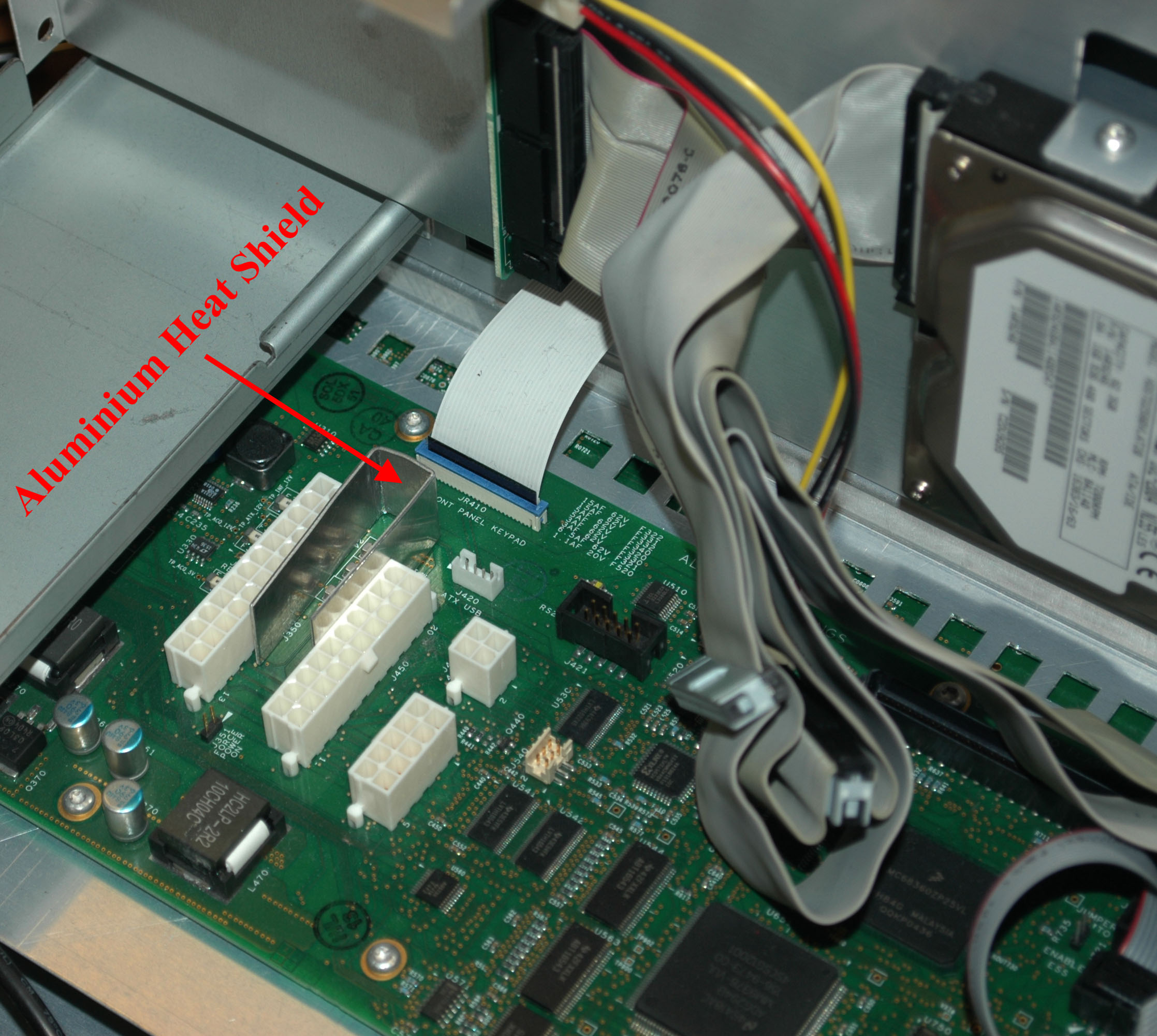
Figure 4: Photo showing the use of a custom-made aluminium heat shield for protecting the ATX power connectors from heat damage during fuse replacement.
The other common problem with these instruments is failed hard drives. Luckily these can be replaced with any standard ATA drive of at least the capacity of the original. If you have an identical instrument on hand do a disk clone between the good drive and the new drive. Else, you will have to find a copy of the recovery CDs…
As mentioned above some of the motherboards fail due to fractured BGA balls connecting the CPU socket to the board. The symptoms of this problem can be the same as the failed capacitor; the power light and fans comes on but the system never boots. However, it can also cause intermittent booting problems or crashes during operation. To determine if the CPU socket is indeed the problem, open the analyser and using your fingers apply considerable pressure to one side of the CPU cooler assembly, straining the motherboard by several millimetres. With the cooler held in this position, attempt to boot the system and note the result. Next, apply the same amount of pressure to the opposite side of the cooler assembly, bending the motherboard in the opposite direction. Again try to boot the system. Repeat the experiment for the remaining two sides of the cooler. If the results are not the same, i.e. the system boots with pressure on one side but not the other, then the socket is most likely damaged. To be sure, remove the cooler and reseat the CPU, then repeat the experiment. I have had some luck reflowing the sockets using an IR board preheater and the hot air rework station, but the results tend to be inconsistent and not always reliable. I thus recommend replacing the motherboard if this problem is present.
Finally, there was an interesting problem with just one of the analysers causing the power light to illuminate only dimly. This was caused by a cracked trace on the silver-ink screen printed PCB for the power switch. Where this PCB was bent around the corner of the LCD unit, the protective covering over the silver traces cracked, damaging the trace and allowing moisture to corrode the remaining silver, thus causing a high-resistance connection. Boards such as this can be repaired with silver epoxy (I like MG Chemicals P/N 8331 for this purpose) after removing the protective coating over the damaged area. Protect the repair from future oxidation using a over-coating of super glue when finished. See Figure 5.
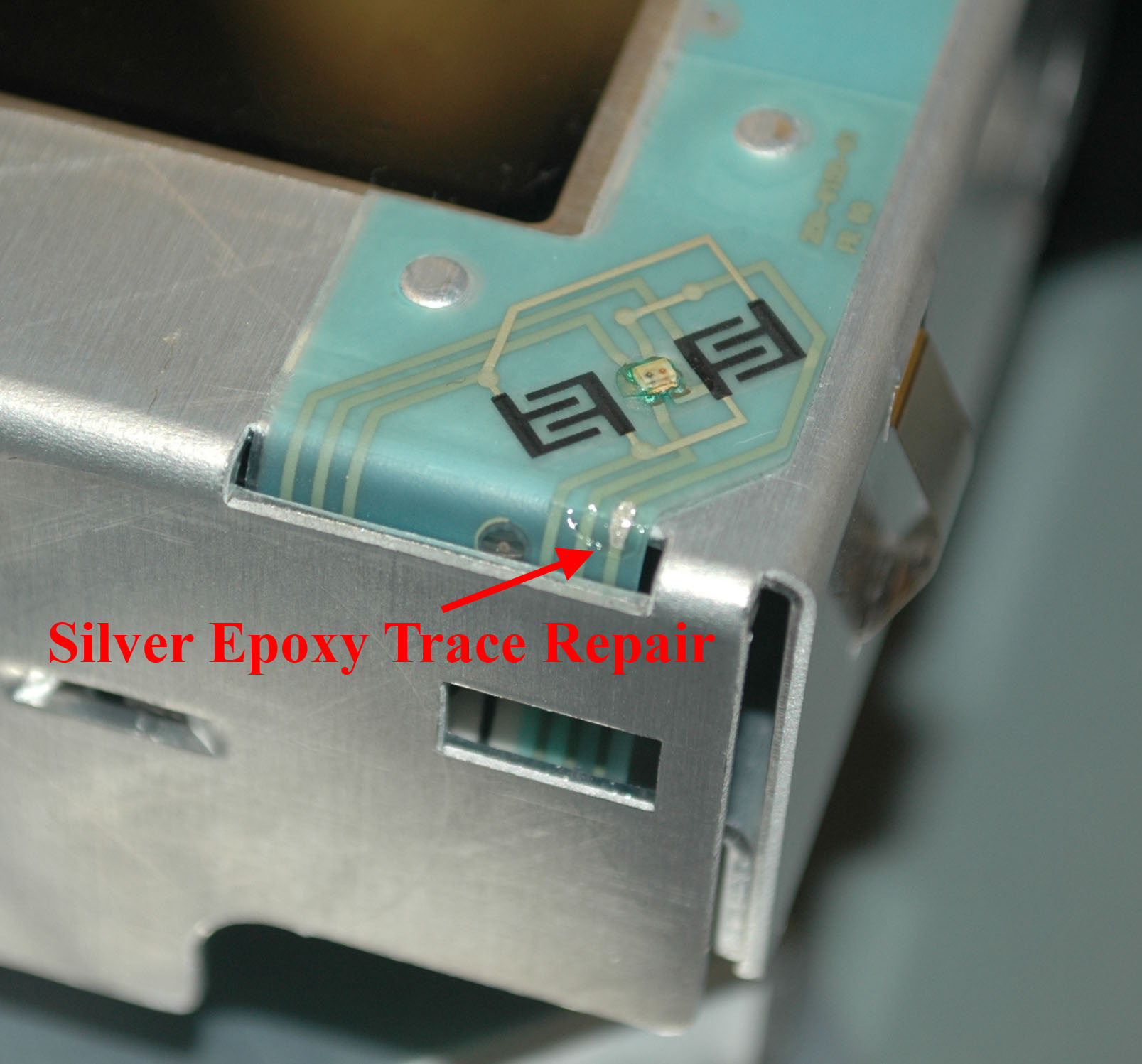
Figure 5: Repair to the power switch
Hope this helps someone!
-Matthew D’Asaro
First, thanks for sharing your troubleshooting tips. Good work. Saved a lot of excellent Logic Analyzers from an early demise. And also saved your colleges budget a few hundred $K avoiding purchase off replacements.
Did you swap BIOS chips or use a software utility to make a backup from a working board then flash it to the replacement?
Thanks for the comment. I actually swapped the physical chips, but it would be just as easy to use a universal programmer to copy the contents. I don’t know how to do it through the BIOS software though – probably highly proprietary.
-Matthew
Intel motherboards allow you to load a custom splash screen so probably a standard bios. http://www.intel.com/content/www/us/en/support/boards-and-kits/desktop-boards/000006606.html
Thanks! That is good to know.
-Matthew
i am looking for TLA-5000 software can you please help me in finding the software as well?Thank you.
Check in the “Schematics and Resources” section. Enjoy!
-Matthew
found it. thank you so much. 🙂
Hello I have a TLA 5201 and our problem is that lcd is black, but i can see everything on an an external monitor. Can you help me?
Thanks
Not sure on that one. Check the LCD backlight by shining a flashlight into the screen and seeing if there is a dark image present.
-Matthew D’Asaro